Advertisement
Available languages
Available languages
Quick Links
STYLE SELECTIONS and logo design are trademarks or
registered trademarks of LF, LLC. All rights reserved.
Serial Number__________________
Purchase Date__________________
Thank you for purchasing this STYLE SELECTIONS product.
Questions, problems or missing parts?
Before returning contact us on:
, 8 a.m. - 8 p.m., EST, Monday - Sunday or
877-888-8225
SG24400
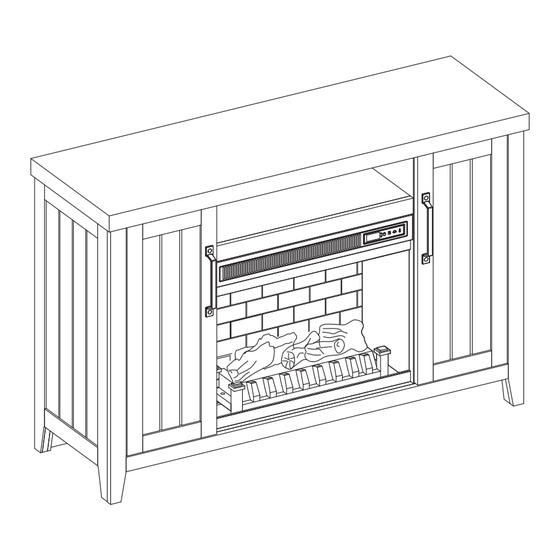
48-IN ELECTRIC
ATTACH YOUR RECEIPT HERE
ascs@lowes.com.
1
ITEM #5703822
MODEL #1730MFP-48-23-500
FIREPLACE
Español p. 23
Advertisement

Subscribe to Our Youtube Channel
Related Manuals for LF Style selections 1730MFP-48-23-500


Summary of Contents for LF Style selections 1730MFP-48-23-500
- Page 1 ITEM #5703822 MODEL #1730MFP-48-23-500 48-IN ELECTRIC FIREPLACE STYLE SELECTIONS and logo design are trademarks or registered trademarks of LF, LLC. All rights reserved. Español p. 23 ATTACH YOUR RECEIPT HERE Serial Number__________________ Purchase Date__________________ Thank you for purchasing this STYLE SELECTIONS product.
- Page 2 TABLE OF CONTENTS Package Contents ..........................3 Hardware Contents..........................4 Safety Information ..........................4 Preparation ............................8 Assembly Instructions.......................... 8 Maximum Recommended Weight Loads ................... 16 Operating Instructions ........................17 Care And Maintenance ........................19 Troubleshooting ..........................20 One-Year Limited Warranty ....................... 21 Replacement Parts List ........................
- Page 3 PACKAGE CONTENTS PART DESCRIPTION QUANTITY PART DESCRIPTION QUANTITY Shelf Center Shelf Fireplace Brick Wall Left Middle Wall Fire Log Right Middle Wall Fireplace Grate Left Outer Wall Remote Control Right Outer Wall (Battery) Fireplace Glass Front Left Door Base Panel Right Door Base Panel Back Rail Center Back Panel...
- Page 4 HARDWARE CONTENTS (NOT SHOWN ACTUAL SIZE) PART DESCRIPTION QUANTITY Shelf Pin Bolt Bolt with Knob Tip Restraint Hardware Touch-up Pen Back panel mounting hardware with screw SAFETY INFORMATION Please read and understand this entire manual before • Reorient or relocate the receiving antenna. attempting to assemble, operate or install the product.
- Page 5 SAFETY INFORMATION (CONTINUED) • DO NOT route cord under furniture or appliances. Modifications not approved by the party responsible Arrange cord away from traffic areas and where it for compliance could void user’s authority to operate the equipment. will not be tripped over. •...
- Page 6 SAFETY INFORMATION (CONTINUED) • To avoid electric shock, fire, or injury, review the • To disconnect this appliance, turn controls to the assembly instruction to confirm that the appropriate OFF position, then remove plug from outlet. critical components and accessories are being used •...
- Page 7 SAFETY INFORMATION (CONTINUED) Electrical Connection Grounding Instructions • A 15-Amp, 120-volt, 60 Hz circuit with a properly • This heater is for use on 120-volt. The cord has a grounded outlet is required. Preferably, the plug as shown below. See illustration or grounding fireplace will be on a dedicated circuit as other instruction.
- Page 8 PREPARATION Before beginning assembly of product, make sure all parts are present. Compare parts with package contents list and hardware contents list. If any part is missing or damaged, do not attempt to assemble the product. Estimated Assembly Time: 50 minutes Tools Required for Assembly (not included): Phillips screwdriver ASSEMBLY INSTRUCTIONS...
- Page 9 ASSEMBLY INSTRUCTIONS (CONTINUED) Insert the assembled base panel back rail (S) and base panel support (T) into the holes on the base panel (R). Using the Phillips head screwdriver to turn the locking nut in clockwise direction up to 180° from the connection joint to properly secure the panels.
- Page 10 ASSEMBLY INSTRUCTIONS (CONTINUED) 4. Attach the middle walls (C, D) into the holes in the middle of the base panel (R). Turn the locking nut in clockwise direction up to 180° from the connection joint to properly secure the walls. 5.
- Page 11 ASSEMBLY INSTRUCTIONS (CONTINUED) 6. Tilt the middle walls (C, D) slightly outwards and attach the center shelf (B) to the middle walls. Make sure the middle walls are pushed back to vertical position to secure the center shelf. 7. As shown in the diagram, insert the center back panel (I) and back panels (J) along the grooves of the middle walls (C, D) and outer walls (E, F).
- Page 12 ASSEMBLY INSTRUCTIONS (CONTINUED) 8. Assemble the top (A) onto the middle walls (C, D) and outer walls (E, F). Turn the locking nut in clockwise direction up to 180° from the connection joint to properly secure the top. 9. Insert shelf pins (AA) at desired height, ensuring they are level.
- Page 13 ASSEMBLY INSTRUCTIONS (CONTINUED) 10. Insert the top pin of the right door (H) into the hole of the plastic nut under the top (A). Pull the latch to re-tract the pin on the bottom of the right door (H) and position it over the hole of the plastic nut on the base panel (R).
- Page 14 ASSEMBLY INSTRUCTIONS (CONTINUED) 12. Remove the film from the adhesive on the top of the fireplace grate (N) and place the fire log (M) on the center of the fireplace grate (N). 13. Insert the pins at the fireplace glass front (Q) onto the holes of the plastic nuts on the base panel (R).
- Page 15 ASSEMBLY INSTRUCTIONS (CONTINUED) 14. Secure the back panels (J) and center back panel (I) to the product using the back panel mounting hardware (KK), screwing the screws by Phillips screwdriver (As shown in diagram 14). Hardware Used Back panel mounting x 12 hardware with screw WARNING: You must install the tip restraint...
- Page 16 MAXIMUM RECOMMENDED WEIGHT LOADS FITS UP TO MOST 127 cm / 50 in FLAT PANEL TVS MAXIMUM LOAD 26.3 kg / 58 lb MAXIMUM LOAD 9.07 kg / 20 lb MAXIMUM LOAD 6.8 kg / 15 lb MAXIMUM LOAD 6.8 kg / 15 lb MAXIMUM LOAD 6.8 kg / 15 lb MAXIMUM LOAD 6.8 kg / 15 lb CAUTION: This console is intended for use with flat panel TV’s only.
- Page 17 OPERATING INSTRUCTIONS Control Panel Remote Control To use the remote control, first insert two AAA batteries (included) into the remote control. Ensure the polarities of the batteries match the inside of the battery compartment. Controls and Display The control panel will display the heater setting when the unit power is turned ON. Whichever control icon you press will display the current setting of the corresponding function.
- Page 18 OPERATING INSTRUCTIONS (CONTINUED) Heater Function (Control Panel Only) • Press the HEATER ICON to display the current heater setting. • Press the HEATER ICON again to scroll down through the heater settings. Note: Long-hold the icon to quickly scroll through settings. •...
- Page 19 CARE AND MAINTENANCE • Make sure the unit is turned OFF, unplugged and the heating elements of heater are cool whenever you are cleaning the heater or fireplace. • Clean the metal trim using a water-dampened soft, clean cloth. DO NOT use brass polish or household cleaners as these products will damage the metal trim.
- Page 20 TROUBLESHOOTING PROBLEM POSSIBLE CAUSE CORRECTIVE ACTION Error E1 displayed on The overheat sensor has Unplug unit, wait 15-20 minutes, then the sensor will reset control panel. been engaged. itself. Plug the unit back in and turn on the heater. If the problem persists, call customer service.
- Page 21 ONE-YEAR LIMITED WARRANTY The manufacturer warrants that your new electric fireplace is free from manufacturing and material defects for a period of one year from date of purchase, subject to the following conditions and limitations. Install and operate this electric fireplace in accordance with the installation and operating instructions furnished with the product at all times.
- Page 22 REPLACEMENT PARTS LIST For replacement parts, call our customer service department at 877-888-8225 8 a.m. - 8 p.m., EST, Monday - Sunday. You could also contact us at ascs@lowes.com. PART DESCRIPTION PART # Fire Log FIRE LOG 1 Fireplace Grate GRATE A Remote Control RC-HE85EL03...
- Page 23 ARTÍCULO #5703822 MODELO #1730MFP-48-23-500 121.92 CM CHIMENEA ELÉCTRICA STYLE SELECTIONS y el diseño del logotipo son marcas comerciales o marcas registradas de LF, LLC. Todos los derechos reservados. ADJUNTE SU RECIBO AQUÍ Número de serie__________________ Fecha de compra__________________ Gracias por comprar este producto STYLE SELECTIONS .
- Page 24 ÍNDICE Contenido del paquete ........................25 Aditamentos............................26 Información de seguridad ........................26 Preparación ............................30 Instrucciones de ensamblaje ......................30 Cargas máximas de peso recomendadas ..................38 Instrucciones de funcionamiento ....................... 39 Cuidado y mantenimiento ........................41 Solución de problemas ........................42 Garantía limitada de un año ......................
- Page 25 CONTENIDO DEL PAQUETE PIEZA DESCRIPCIÓN CANTIDAD PIEZA DESCRIPCIÓN CANTIDAD Parte superior Estante Repisa central Pared de ladrillos de la chimenea Pared del medio izquierda Leño para chimenea Pared del medio Rejilla para chimenea derecha Control remoto (batería) Pared exterior izquierda Parte frontal del vidrio Pared exterior derecha de la chimenea...
- Page 26 ADITAMENTOS (NO SE MUESTRAN EN TAMAÑO REAL) PIEZA DESCRIPCIÓN CANTIDAD Pasador de repisa Perno Perno con perilla Aditamento de contención antivuelcos Aplicador de retoque Aditamentos de montaje del panel posterior con tornillo INFORMACIÓN DE SEGURIDAD Lea y comprenda completamente este manual antes •...
- Page 27 INFORMACIÓN DE SEGURIDAD (CONTINUACIÓN) • NO pase el cable debajo de alfombras. NO cubra Las modificaciones que no estén aprobadas por la el cable con alfombras de pasillo, tapetes u objetos parte responsable del cumplimiento podrían anular la autorización del usuario para utilizar el equipo. similares.
- Page 28 INFORMACIÓN DE SEGURIDAD (CONTINUACIÓN) • Cada superficie prevista para soportar una carga • “ADVERTENCIA: la colocación de equipos de audio debe tener una declaración correspondiente en las o video en muebles no diseñados específicamente instrucciones de uso que indica la carga máxima en para soportar tales equipos puede causar la muerte kilogramos (libras) prevista para esa superficie.
- Page 29 INFORMACIÓN DE SEGURIDAD (CONTINUACIÓN) Conexión eléctrica Instrucciones de puesta a tierra • Se requiere un circuito de 15 amperios, 120 voltios, • Este calentador se diseñó para usarse con 60 Hz con un tomacorriente con la debida puesta 120 voltios. El cable tiene un enchufe como se a tierra.
- Page 30 PREPARACIÓN Antes de empezar a ensamblar el producto, asegúrese de que todas las piezas estén presentes. Compare las piezas con la lista del contenido del paquete y de los aditamentos. No intente ensamblar, instalar o usar el producto si faltan piezas o si están dañadas. Tiempo estimado de ensamblaje: 50 minutos Herramientas necesarias para el...
- Page 31 INSTRUCCIONES DE ENSAMBLAJE (CONTINUACIÓN) 2. Coloque el riel posterior del panel base ensamblado (S) y el soporte del panel base (T) en los orificios del panel base (R). Con el destornillador Phillips, gire la contratuerca en dirección de las manecillas delreloj hasta 180° desde la junta de conexión paraasegurar correctamente los paneles.
- Page 32 INSTRUCCIONES DE ENSAMBLAJE (CONTINUACIÓN) 4. Fije las paredes centrales (C, D) en los orificios del centro del panel base (R). Gire la contratuerca en dirección de las manecillas del reloj hasta 180° desde la junta de conexión para asegurar correctamente las paredes. 5.
- Page 33 INSTRUCCIONES DE ENSAMBLAJE (CONTINUACIÓN) 6. Incline las paredes centrales (C, D) ligeramente hacia afuera y fije el estante central (B) a las paredes centrales. Asegúrese de que las paredes centrales estén hacia atrás, en posición vertical, para asegurar el estante central. 7.
- Page 34 INSTRUCCIONES DE ENSAMBLAJE (CONTINUACIÓN) 8. Ensamble la parte superior (A) en las paredes centrales (C, D) y las paredes exteriores (E, F). Gire la contratuerca en dirección de las manecillas del reloj hasta 180° desde la junta de conexión para asegurar correctamente la parte superior.
- Page 35 INSTRUCCIONES DE ENSAMBLAJE (CONTINUACIÓN) 10. Introduzca el pasador superior de la puerta derecha (H) en el orificio de la tuerca de plástico situada debajo de la parte superior (A). Tire el pestillo para retraer el pasador de la parte inferior de la puerta derecha (H) y colóquelo sobre el orificio de la tuerca de plástico en el panel base (R).
- Page 36 INSTRUCCIONES DE ENSAMBLAJE (CONTINUACIÓN) 12. Retire la película del adhesivo en la parte superior de la rejilla para chimenea (N) y coloque el leño para chimenea (M) en el centro de la rejilla para chimenea (N). 13. Inserte los pasadores del frente del cristal de la chimenea (Q) en los orificios de las tuercas de plástico del panel base (R).
- Page 37 INSTRUCCIONES DE ENSAMBLAJE (CONTINUACIÓN) 14. Asegure los paneles posteriores (J) y el panel posterior central (I) al producto utilizando los aditamentos de montaje del panel posterior (KK), atornillando los tornillos con un destornillador Phillips (como se muestra en el diagrama 14). Aditamentos utilizados Aditamentos de montaje del panel...
- Page 38 CARGAS MÁXIMAS DE PESO RECOMENDADAS SE ADAPTA A LA MAYORÍA DE LOS TELEVISORES DE PANTALLA PLANA DE 127 cm/50 pulg. CAPACIDAD MÁXIMA: 26,3 kg/58 lb CAPACIDAD MÁXIMA: 9,07 kg/20 lb CAPACIDAD MÁXIMA: 6,8 kg/15 lb CAPACIDAD MÁXIMA: 6,8 kg/15 lb CAPACIDAD MÁXIMA: 6,8 kg/15 lb CAPACIDAD MÁXIMA: 6,8 kg/15 lb PRECAUCIÓN: esta consola está...
- Page 39 INSTRUCCIONES DE FUNCIONAMIENTO Panel de control Control remoto Para usar el control remoto, primero inserte dos baterías AAA (incluidas) en el control remoto. Asegúrese de que las polaridades de las baterías coincidan con el interior del compartimento de la batería. Controles y pantalla El panel de control mostrará...
- Page 40 INSTRUCCIONES DE FUNCIONAMIENTO (CONTINUACIÓN) Función de calentador (solo panel de control) • Presione el ÍCONO DE CALENTADOR para mostrar la configuración actual del calentador. • Presione el ÍCONO DE CALENTADOR nuevamente para desplazarse hacia abajo a través de la configuración del calentador. Nota: mantenga presionado el ícono para desplazarse rápidamente por la configuración.
- Page 41 CUIDADO Y MANTENIMIENTO • Asegúrese de que la unidad esté APAGADA, desenchufada y que los elementos de calefacción estén fríos cada vez que limpie el calentador o la chimenea. • Limpie el borde metálico con un paño suave y limpio humedecido con agua. NO use pulidores de latón ni limpiadores domésticos, ya que estos productos dañarán el borde metálico.
- Page 42 SOLUCIÓN DE PROBLEMAS PROBLEMA CAUSA POSIBLE ACCIÓN CORRECTIVA El error E1 se muestra Se ha activado el sensor Desenchufe la unidad, espere de 15 a 20 minutos, luego el en el panel de control. de sobrecalentamiento. sensor se reiniciará automáticamente. Vuelva a enchufar la unidad y encienda el calentador.
- Page 43 GARANTÍA LIMITADA DE UN AÑO El fabricante garantiza que su nueva chimenea eléctrica no presentará defectos de fabricación ni en los materiales durante un período de un año a partir de la fecha de compra, siempre y cuando se cumplan las siguientes condiciones y limitaciones. Instale y use el la chimenea eléctrica según lo indican las instrucciones de instalación y funcionamiento provistas con el producto en todo momento.
- Page 44 LISTA DE PIEZAS DE REPUESTO Para obtener piezas de repuesto, llame a nuestro Departamento de Servicio al Cliente al , de lunes a domingo de 8 a.m. a 8 p.m., hora estándar del Este. También puede 877-888-8225 ponerse en contacto con nosotros en ascs@lowes.com.
Need help?
Do you have a question about the Style selections 1730MFP-48-23-500 and is the answer not in the manual?
Questions and answers