Advertisement
Available languages
Available languages
Quick Links
ALLEN + ROTH and logo design are trademarks or
registered trademarks of LF, LLC. All rights reserved.
Serial Number__________________
Purchase Date__________________
Thank you for purchasing this ALLEN + ROTH product.
Questions, problems or missing parts?
Before returning contact us on:
, 8 a.m. - 8 p.m., EST, Monday - Sunday or
866-439-9800
SG24392
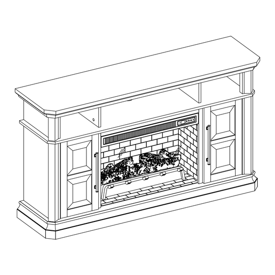
MODEL #1010MFP-58-26-501
58-IN ELECTRIC
ATTACH YOUR RECEIPT HERE
ascs@lowes.com.
1
ITEM #5691735
FIREPLACE
Español p. 29
Advertisement

Subscribe to Our Youtube Channel
Related Manuals for LF allen+roth 1010MFP-58-26-501


Summary of Contents for LF allen+roth 1010MFP-58-26-501
- Page 1 ITEM #5691735 MODEL #1010MFP-58-26-501 ALLEN + ROTH and logo design are trademarks or registered trademarks of LF, LLC. All rights reserved. 58-IN ELECTRIC FIREPLACE Español p. 29 ATTACH YOUR RECEIPT HERE Serial Number__________________ Purchase Date__________________ Thank you for purchasing this ALLEN + ROTH product.
- Page 2 TABLE OF CONTENTS Package Contents ..........................3 Hardware Contents..........................4 Safety Information ..........................4 Preparation ............................8 Assembly Instructions.......................... 8 Maximum Recommended Weight Loads ................... 22 Operating Instructions ........................23 Care And Maintenance ........................25 Troubleshooting ..........................26 One-Year Limited Warranty ....................... 27 Replacement Parts List ........................
- Page 3 PACKAGE CONTENTS PART DESCRIPTION QUANTITY PART DESCRIPTION QUANTITY Fireplace Brick Wall Corner Panel Fire Log Partition Panel Fireplace Grate Center Shelf And Remote Control Heater (with Battery) Left Middle Wall Center Back Panel Right Middle Wall Back Panel Outer Wall Fireplace Glass Front Shelf Base...
- Page 4 HARDWARE CONTENTS (NOT SHOWN ACTUAL SIZE) PART DESCRIPTION QUANTITY PART DESCRIPTION QUANTITY Hinge Wooden Dowel Short Screw Door Pull Connecting Rod Long Screw Locknut L-Bracket Back panel mounting Screw hardware with screw Touch-up Pen Shelf Pin Tip Restraint Hardware Hinge Screw SAFETY INFORMATION Please read and understand this entire manual before •...
- Page 5 SAFETY INFORMATION (CONTINUED) Modifications not approved by the party responsible • DO NOT route cord under furniture or appliances. for compliance could void user’s authority to operate Arrange cord away from traffic areas and where it the equipment. will not be tripped over. •...
- Page 6 SAFETY INFORMATION (CONTINUED) • To avoid electric shock, fire, or injury, review the • To disconnect this appliance, turn controls to the assembly instruction to confirm that the appropriate OFF position, then remove plug from outlet. critical components and accessories are being used •...
- Page 7 SAFETY INFORMATION (CONTINUED) Electrical Connection Grounding Instructions • A 15-Amp, 120-volt, 60 Hz circuit with a properly • This heater is for use on 120-volt. The cord has a grounded outlet is required. Preferably, the plug as shown below. See illustration or grounding fireplace will be on a dedicated circuit as other instruction.
- Page 8 PREPARATION Before beginning assembly of product, make sure all parts are present. Compare parts with package contents list and hardware contents list. If any part is missing or damaged, do not attempt to assemble the product. Estimated Assembly Time: 40 minutes Tools Required for Assembly (not included): Phillips screwdriver ASSEMBLY INSTRUCTIONS...
- Page 9 ASSEMBLY INSTRUCTIONS (CONTINUED) 2. As shown in the diagram, insert four wooden dowels (AA) into the holes of base (Q). Attach the left middle wall (E) and right middle wall (F), secure with screwing four locknuts (DD) by Phillips screwdriver. Hardware Used Wooden Dowel Locknut...
- Page 10 ASSEMBLY INSTRUCTIONS (CONTINUED) As shown in the diagram, insert the back panels (L) along the grooves of the middle walls (E, F) and outer walls (G). 5. Attach the fireplace glass front (R), lowering it into the front groove on base (Q). Secure the glass by turning the pre-assembled plastic knobs.
- Page 11 ASSEMBLY INSTRUCTIONS (CONTINUED) Screw eight connecting rods (CC) into the designated holes on the top of the center shelf and heater (D). Hardware Used Connecting Rod 7. Insert ten wooden dowels (AA) into the top outer holes of the outer walls (G) and middle walls (E, F).
- Page 12 ASSEMBLY INSTRUCTIONS 8. Adjust the metal plate of the left middle wall panel (E) and right middle wall panel (F) to align with the corresponding holes on the center shelf and heater (D). Secure the center shelf and heater (D) with two short screws (BB).
- Page 13 ASSEMBLY INSTRUCTIONS (CONTINUED) Insert wooden dowels (AA) into the top holes of the center shelf and heater (D), align the holes in the corner panels (B) and the partition panels (C) with the inserted dowels and lower into place. Secure the corner panels (B) and partition panels (C) to the center shelf and heater (D) using eight locknuts (DD).
- Page 14 ASSEMBLY INSTRUCTIONS (CONTINUED) Screw eight connecting rods (CC) into the designated holes on the back of the top (A). Hardware Used Connecting Rod Insert wooden dowels (AA) into the top holes of the corner panels (B) and the partition panels (C), align the holes in the top (A) with the inserted dowels and lower into place.
- Page 15 ASSEMBLY INSTRUCTIONS (CONTINUED) Secure the back panels (L) and center back panel (K) to the product using the back panel mounting hardware with screw (EE), screwing the screws by Phillips screwdriver (As shown in diagram 14). Hardware Used Back panel mounting x 14 hardware with screw Insert the shelf pins (FF) at the desired height,...
- Page 16 ASSEMBLY INSTRUCTIONS (CONTINUED) Place the hinges (HH) into predrilled hole on the door (I), securing with two hinge screws (GG). Repeat for the remaining hinges (HH). Hardware Used Hinge Screw Hinge Place the door pull (II) into predrilled hole on the door (I), securing with two door pull screws.
- Page 17 ASSEMBLY INSTRUCTIONS (CONTINUED) Install the doors I. Pick up door (I) and attach it to left outer wall (G) by engaging both door hinges simultaneously. Please follow the steps below to combine the door hinges together. i. Extend both hinge arms on the door (I) to open position. ii.
- Page 18 ASSEMBLY INSTRUCTIONS (CONTINUED) Place the fireplace grate (N) by inserting the bottom pins into the holes in the base (Q), securing with two long screw (JJ) by Phillips screwdriver. Hardware Used Long Screw Remove the film from the adhesive on the top of the fireplace grate (N) and place the fire log (M) on the center of the fireplace grate (N).
- Page 19 ASSEMBLY INSTRUCTIONS (CONTINUED) Screw two L-bracket (KK) onto the fireplace brick wall (J) using four screws (LL). Hardware Used L-Bracket Screw Insert the fireplace brick wall (J) into the mantel by haft way, put the USB cable from the heater pass through the hole on the back of fireplace brick wall (J).
- Page 20 ASSEMBLY INSTRUCTIONS (CONTINUED) 24. Insert the fireplace brick wall (J) into the mantel, slotting it into the grooves on the base ). Secure it by using two screws (LL) into the L-bracket (KK). Hardware Used Screw NOTE: Use the pre-assembled levelers on the base of the fireplace to level the unit.
- Page 21 ASSEMBLY INSTRUCTIONS (CONTINUED) WARNING: You must install the tip restraint hardware to help prevent any accidents or damage (iii) to the unit. We strongly recommend attaching the tip Wall Stud restraint hardware to a wall stud and your unit. For all other wall types, please visit your local hardware (ii) store to obtain the proper hardware.
- Page 22 MAXIMUM RECOMMENDED WEIGHT LOADS FITS UP TO MOST 132.08 cm / 52 in FLAT PANEL TVS MAXIMUM LOAD 22.72 kg / 50 lb MAXIMUM LOAD 6.8 kg / 15 lb MAXIMUM LOAD 16.36 kg / 36 lb MAXIMUM LOAD 6.8 kg / 15 lb MAXIMUM LOAD 4.54 kg / 10 lb MAXIMUM LOAD 4.54 kg / 10 lb MAXIMUM LOAD 4.54 kg / 10 lb...
- Page 23 OPERATING INSTRUCTIONS Control Panel Remote Control To use the remote control, first insert two AAA batteries (included) into the remote control. Ensure the polarities of the batteries match the inside of the battery compartment. Controls and Display The control panel will display the heater setting when the unit power is turned ON. Whichever control icon you press will display the current setting of the corresponding function.
- Page 24 OPERATING INSTRUCTIONS (CONTINUED) Heater Function (Control Panel Only) • Press the HEATER ICON to display the current heater setting. • Press the HEATER ICON again to scroll down through the heater settings. Note: Long-hold the icon to quickly scroll through settings. •...
- Page 25 CARE AND MAINTENANCE • Make sure the unit is turned OFF, unplugged and the heating elements of heater are cool whenever you are cleaning the heater or fireplace. • Clean the metal trim using a water-dampened soft, clean cloth. DO NOT use brass polish or household cleaners as these products will damage the metal trim.
- Page 26 TROUBLESHOOTING PROBLEM POSSIBLE CAUSE CORRECTIVE ACTION Error E1 displayed on The overheat sensor has Unplug unit, wait 15-20 minutes, then the sensor will reset control panel. been engaged. itself. Plug the unit back in and turn on the heater. If the problem persists, call customer service.
- Page 27 ONE-YEAR LIMITED WARRANTY The manufacturer warrants that your new electric fireplace is free from manufacturing and material defects for a period of one year from date of purchase, subject to the following conditions and limitations. Install and operate this electric fireplace in accordance with the installation and operating instructions furnished with the product at all times.
- Page 28 REPLACEMENT PARTS LIST For replacement parts, call our customer service department at 866-439-9800 8 a.m. - 8 p.m., EST, Monday - Sunday. You could also contact us at ascs@lowes.com. O FF O PP O I I PART DESCRIPTION PART # Fire Log 2 Fire Log Fire Grate B...
- Page 29 ARTÍCULO #5691735 MODELO #1010MFP-58-26-501 ALLEN+ROTH y el diseño del logotipo son marcas 147.32 CM CHIMENEA comerciales o marcas registradas de LF, LLC. Todos los derechos reservados. ELÉCTRICA ADJUNTE SU RECIBO AQUÍ Número de serie Fecha de compra Gracias por comprar este producto ALLEN+ROTH.
- Page 30 ÍNDICE Contenido del paquete ........................31 Aditamentos ............................32 Información de seguridad ........................32 Preparación ............................36 Instrucciones de ensamblaje ......................36 Cargas máximas de peso recomendadas ..................Instrucciones de funcionamiento ....................... Cuidado y mantenimiento ......................... Solución de problemas ........................Garantía limitada de un año ......................
- Page 31 CONTENIDO DEL PAQUETE PIEZA DESCRIPCIÓN CANTIDAD PIEZA DESCRIPCIÓN CANTIDAD Pared de ladrillos de Parte superior la chimenea Panel de esquina Leños para fuego Panel de separación Parrilla para chimenea Estante central Control remoto y calefactor (con batería) Pared central izquierda Pared central derecha Panel posterior central Pared exterior...
- Page 32 ADITAMENTOS (NO SE MUESTRAN EN TAMAÑO REAL) PIEZA DESCRIPCIÓN CANTIDAD PIEZA DESCRIPCIÓN CANTIDAD Bisagra Espiga de madera Tornillo corto Tirador de puerta Varilla de conexión Tornillo largo Contratuerca Soporte en L Aditamentos de montaje del Tornillo panel posterior con tornillo Aplicador de retoque Soporte para estante Aditamento de contención...
- Page 33 INFORMACIÓN DE SEGURIDAD (CONTINUACIÓN) Las modificaciones que no estén aprobadas por la • NO pase el cable debajo de muebles o parte responsable del cumplimiento con las electrodomésticos. Coloque el cable lejos de zonas regulaciones podrían anular la autorización del de tránsito y donde nadie se pueda tropezar y caer.
- Page 34 INFORMACIÓN DE SEGURIDAD (CONTINUACIÓN) • Para evitar el riesgo de descargas eléctricas, • Para desconectar este electrodoméstico, gire los incendios o lesiones, revise las instrucciones de controles a la posición de APAGADO y luego retire ensamblaje para confirmar que los componentes el enchufe del tomacorriente.
- Page 35 INFORMACIÓN DE SEGURIDAD (CONTINUACIÓN) Conexión eléctrica Instrucciones de puesta a tierra • Se requiere un circuito de 15 amperios, • Este calefactor está diseñado para su uso en 120 voltios y 60 Hz con un tomacorriente con la 120 voltios. El cable tiene un enchufe, como debida puesta a tierra.
- Page 36 PREPARACIÓN Antes de comenzar a ensamblar el producto, asegúrese de tener todas las piezas. Compare las piezas con la lista del contenido del paquete y la lista de aditamentos. No intente ensamblar el producto si falta alguna pieza o si están dañadas. Tiempo aproximado de ensamblaje: 40 minutos Herramientas necesarias para el ensamblaje...
- Page 37 INSTRUCCIONES DE ENSAMBLAJE (CONTINUACIÓN) 2. Como se muestra en el diagrama, inserte cuatro espigas de madera (AA) en los orificios de la base (Q). Fije la pared central izquierda (E) y la pared central derecha (F), asegúrelo con cuatro contratuercas (DD) con un destornillador Phillips. Aditamentos utilizados Espiga de madera Contratuerca...
- Page 38 INSTRUCCIONES DE ENSAMBLAJE (CONTINUACIÓN) Como se muestra en el diagrama, inserte los paneles posteriores (L) a lo largo de las ranuras de las paredes centrales (E, F) y las paredes exteriores (G). 5. Baje el vidrio frontal de la chimenea (R) en la ranura frontal de la base (Q) para colocarlo.
- Page 39 INSTRUCCIONES DE ENSAMBLAJE (CONTINUACIÓN) Atornille ocho varillas de conexión (CC) en los orificios designados en la parte superior del estante central y el calefactor (D). Aditamentos utilizados Varilla de conexión 7. Inserte diez espigas de madera (AA) en los orificios exteriores superiores de las paredes exteriores (G) y las paredes centrales (E, F).
- Page 40 INSTRUCCIONES DE ENSAMBLAJE 8. Ajuste la placa de metal del panel de la pared central izquierda (E) y del panel de la pared central derecha (F) para alinearlos con los orificios correspondientes en el estante central y el calefactor (D). Asegure el estante central y el calefactor (D) con dos tornillos cortos (BB).
- Page 41 INSTRUCCIONES DE ENSAMBLAJE (CONTINUACIÓN) 10. Inserte espigas de madera (AA) en los orificios superiores del estante central y el calefactor (D), alinee los orificios en los paneles de las esquinas (B) y los paneles divisorios (C) con las espigas insertadas y baje hasta encajar en su lugar.
- Page 42 INSTRUCCIONES DE ENSAMBLAJE (CONTINUACIÓN) Enrosque ocho varillas de conexión (CC) en los orificios designados de la parte posterior de la parte superior (A). Aditamentos utilizados Varilla de conexión 13. Inserte espigas de madera (AA) en los orificios superiores de los paneles centrales (B) y los paneles divisorios (C), alinee los orificios de la parte superior (A) con las...
- Page 43 INSTRUCCIONES DE ENSAMBLAJE (CONTINUACIÓN) 14. Asegure los paneles posteriores (L) y el panel posterior central (K) al producto con los aditamentos de montaje del panel posterior con un tornillo (EE), atornillando los tornillos con un destornillador Phillips (como se muestra en el diagrama 14).
- Page 44 INSTRUCCIONES DE ENSAMBLAJE (CONTINUACIÓN) Coloque las bisagras (HH) en el orificio pretaladrado de la puerta (I) y asegúrelas con dos tornillos para bisagra (GG). Repita los mismos pasos para el resto de las bisagras (HH). Aditamentos utilizados Tornillo para bisagra Bisagra Coloque el tirador de puerta (II) en el orificio pretaladrado de la puerta...
- Page 45 INSTRUCCIONES DE ENSAMBLAJE (CONTINUACIÓN) Instale las puertas I. Levante la puerta (I) y fíjela a la pared exterior izquierda (G) al enganchar ambas bisagras de la puerta simultáneamente. Siga los pasos a continuación para combinar las bisagras de la puerta. i.
- Page 46 INSTRUCCIONES DE ENSAMBLAJE (CONTINUACIÓN) Coloque la rejilla de la chimenea (N) al insertar los pasadores inferiores en los orificios de la base (Q), asegurándola con dos tornillos largos (JJ) con un destornillador Phillips. Aditamentos utilizados Tornillo largo 21. Retire la película del adhesivo en la parte superior de la parrilla de la chimenea (N) y coloque los leños para fuego (M) en el centro de la parrilla (N).
- Page 47 INSTRUCCIONES DE ENSAMBLAJE (CONTINUACIÓN) 22. Atornille los dos soportes en L (KK) en la pared de ladrillos de la chimenea (J) con cuatro tornillos (LL). Aditamentos utilizados Soporte en L Tornillo 23. Inserte la pared de ladrillos de la chimenea (J) en la repisa por la manija, pase el cable USB del calefactor a través del orificio en la parte posterior de la pared de ladrillos de la...
- Page 48 INSTRUCCIONES DE ENSAMBLAJE (CONTINUACIÓN) 24. Inserte la pared de ladrillos de la chimenea (J) en la repisa para chimenea, encajándola en las ranuras de la base (Q). Asegure con dos tornillos (LL) en el soporte en L (KK). Aditamentos utilizados Tornillo NOTA: Use los niveladores preensamblados en la base de la chimenea para nivelar la unidad.
- Page 49 INSTRUCCIONES DE ENSAMBLAJE (CONTINUACIÓN) ADVERTENCIA: Debe instalar los aditamentos de contención antivuelcos para ayudar a evitar (iii) Montante cualquier accidente o daños a la unidad. de pared Recomendamos encarecidamente fijar los aditamentos de sujeción de la punta a un montante (ii) de pared y a su unidad.
- Page 50 CARGAS MÁXIMAS DE PESO RECOMENDADAS SE ADAPTA A LA MAYORÍA DE TELEVISORES DE PANTALLA PLANA DE 132,08 cm/52 pulg. CAPACIDAD MÁXIMA 22,72 kg/50 lb CAPACIDAD MÁXIMA: 6,8 kg/15 lb CAPACIDAD MÁXIMA: 16,36 kg/36 lb CAPACIDAD MÁXIMA: 6,8 kg/15 lb CAPACIDAD MÁXIMA: 4,54 kg/10 lb CAPACIDAD MÁXIMA: 4,54 kg/10 lb CAPACIDAD MÁXIMA: 4,54 kg/10 lb CAPACIDAD MÁXIMA: 4,54 kg/10 lb...
- Page 51 INSTRUCCIONES DE FUNCIONAMIENTO Panel de control Control remoto Para usar el control remoto, primero inserte dos baterías AAA (incluidas) en el control remoto. Asegúrese de que las polaridades de las baterías coincidan con el interior del compartimento de la batería. Controles y pantalla El panel de control mostrará...
- Page 52 INSTRUCCIONES DE FUNCIONAMIENTO (CONTINUACIÓN) Función de calentador (solo panel de control) • Presione el ÍCONO DE CALENTADOR para mostrar la configuración actual del calentador. • Presione el ÍCONO DEL CALENTADOR nuevamente para desplazarse hacia abajo a través de la configuración del calentador. Nota: Mantenga presionado el ícono para desplazarse rápidamente por la configuración.
- Page 53 CUIDADO Y MANTENIMIENTO • Asegúrese de que la unidad esté APAGADA, desenchufada y que los elementos de calefacción estén fríos cada vez que limpie el calefactor o la chimenea. • Limpie el borde metálico con un paño suave y limpio humedecido con agua. NO use pulidores de latón ni limpiadores domésticos, ya que estos productos dañan el reborde de metal.
- Page 54 SOLUCIÓN DE PROBLEMAS PROBLEMA CAUSA POSIBLE ACCIÓN CORRECTIVA El error E1 se Se ha activado el sensor Desenchufe la unidad, espere de 15 a 20 minutos, muestra en el panel de sobrecalentamiento. luego el sensor se reiniciará automáticamente. de control. Vuelva a enchufar la unidad y encienda el calentador.
- Page 55 UN AÑO DE GARANTÍA LIMITADA El fabricante garantiza que su nueva chimenea eléctrica no presentará defectos de fabricación ni en los materiales durante un período de un año a partir de la fecha de compra, siempre y cuando se cumplan las siguientes condiciones y limitaciones. Esta chimenea eléctrica se debe instalar y utilizar en todo momento de acuerdo con las instrucciones de instalación y operación proporcionadas con el producto.
- Page 56 LISTA DE PIEZAS DE REPUESTO Para obtener piezas de repuesto, llame a nuestro departamento de Servicio al Cliente al 866-439-9800, de lunes a domingo de 8 a.m. a 8 p.m., hora estándar del Este. También puede ponerse en contacto con nosotros a través de ascs@lowes.com.
Need help?
Do you have a question about the allen+roth 1010MFP-58-26-501 and is the answer not in the manual?
Questions and answers