Advertisement
Available languages
Available languages
Quick Links
ALLEN + ROTH and logo design are trademarks or
registered trademarks of LF, LLC. All rights reserved.
ATTACH YOUR RECEIPT HERE
Serial Number__________________ Purchase Date__________________
Questions, problems, missing parts? Before returning to your retailer, call our customer service
department at 866-439-9800, 8 a.m. - 8 p.m., EST, Monday - Sunday. You could also contact us at
partsplus@lowes.com.
SS23307
welcoming
•
sophisticated
47.5-IN ELECTRIC
1
•
inspiring
ITEM #5228503
FIREPLACE
MODEL #2623FM-23-311
Español p. 28
Advertisement

Related Manuals for LF ALLEN + ROTH 2623FM-23-311


Summary of Contents for LF ALLEN + ROTH 2623FM-23-311
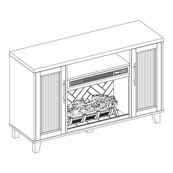
- Page 1 • inspiring ITEM #5228503 47.5-IN ELECTRIC ALLEN + ROTH and logo design are trademarks or registered trademarks of LF, LLC. All rights reserved. FIREPLACE MODEL #2623FM-23-311 Español p. 28 ATTACH YOUR RECEIPT HERE Serial Number__________________ Purchase Date__________________ Questions, problems, missing parts? Before returning to your retailer, call our customer service department at 866-439-9800, 8 a.m.
- Page 2 TABLE OF CONTENTS Package Contents ..........................3 Hardware Contents..........................4 Safety Information ..........................4 Preparation ............................8 Assembly Instructions.......................... 8 Maximum Recommended Weight Loads ................... 20 Operating Instructions ........................21 Care And Maintenance ........................23 Troubleshooting ..........................25 One-Year Limited Warranty ....................... 26 Replacement Parts List ........................
- Page 3 PACKAGE CONTENTS PART DESCRIPTION QUANTITY PART DESCRIPTION QUANTITY Back Panel Center Shelf Fire Log Left Middle Wall Fireplace Grate Right Middle Wall Remote Control (Battery Inside) Left Outer Wall Fireplace Glass Front Right Outer Wall Base Left Door Right Door Center Support Leg Fireplace Brick Wall Shelf...
- Page 4 HARDWARE CONTENTS (NOT SHOWN ACTUAL SIZE) PART DESCRIPTION QUANTITY PART DESCRIPTION QUANTITY Connecting Rod L-Bracket Locknut Screw Wooden Dowel Door Pull Back panel mounting Shelf Pin hardware with screw Touch-up Pen Long Bolt Hinge Bolt Hinge Screw Stopper SAFETY INFORMATION Please read and understand this entire manual before •...
- Page 5 SAFETY INFORMATION (CONTINUED) • DO NOT route cord under furniture or appliances. Modifications not approved by the party responsible Arrange cord away from traffic areas and where it for compliance could void user’s authority to operate the equipment. will not be tripped over. •...
- Page 6 SAFETY INFORMATION (CONTINUED) • To avoid electric shock, fire, or injury, review the • To disconnect this appliance, turn controls to the assembly instruction to confirm that the appropriate OFF position, then remove plug from outlet. critical components and accessories are being used •...
- Page 7 SAFETY INFORMATION (CONTINUED) Electrical Connection Grounding Instructions • A 15-Amp, 120-volt, 60 Hz circuit with a properly • This heater is for use on 120-volt. The cord has a grounded outlet is required. Preferably, the plug as shown below. See illustration or grounding fireplace will be on a dedicated circuit as other instruction.
- Page 8 PREPARATION Before beginning assembly of product, make sure Estimated Assembly Time: 60 minutes all parts are present. Compare parts with package Tools Required for Assembly (not contents list and hardware contents list. If any part is missing or damaged, do not attempt to assemble the included): Phillips screwdriver product.
- Page 9 ASSEMBLY INSTRUCTIONS (CONTINUED) 2. Insert two wooden dowels (CC) into the holes on the left middle wall (C). Attach the center shelf (B) to the left middle wall (C), secure with screwing two locknuts (BB) by Phillips screwdriver. Repeat for the right middle wall (D). Hardware Used Locknut Wooden Dowel...
- Page 10 ASSEMBLY INSTRUCTIONS (CONTINUED) 4. Locate the center support leg (T) and screw into the back of the base (R). 5. Screw eight connecting rods (AA) into the holes on the top of the base (R). Hardware Used Connecting Rod...
- Page 11 ASSEMBLY INSTRUCTIONS (CONTINUED) 6. As shown in the diagram, insert four wooden dowels (CC) into the holes of base (R), align and attach the assembly from step 2 to the base (R), secure with screwing four locknuts (BB) by Phillips screwdriver. Hardware Used Locknut Wooden Dowel...
- Page 12 ASSEMBLY INSTRUCTIONS (CONTINUED) 8. As shown in the diagram, insert the center back panel (K) and back panels (L) along the grooves of the middle walls (C, D) and outer walls (E, F). 9. Screw eight connecting rods (AA) into the designated holes on the back of the top (A).
- Page 13 ASSEMBLY INSTRUCTIONS (CONTINUED) 10. Insert eight wooden dowels (CC) into the top outer holes of the middle walls (C, D) and outer walls (E, F). Attach the top (A), secure with screwing eight locknuts (BB) by Phillips screwdriver. Hardware Used Locknut Wooden Dowel 11.
- Page 14 ASSEMBLY INSTRUCTIONS (CONTINUED) 12. Place the door pull (II) into predrilled hole on the left door (G), securing with two door pull screws. Repeat for the remaining door pull (II). Hardware Used Door Pull 13. Install the doors I. Loosen the screws on the hinge arms and plates pre-attached on the outer walls (E, F). II.
- Page 15 ASSEMBLY INSTRUCTIONS (CONTINUED) 14. If you need to adjust the doors, do so in the following manner. To adjust door up or down, loosen screws (a) on both hinges, adjust door, and retighten screws. To adjust door left or right, turn screws (b) on both hinges, in and out. To adjust door in or out, loosen screws (c) on both hinges, adjust door, and retighten screws.
- Page 16 ASSEMBLY INSTRUCTIONS (CONTINUED) 16. Place the fireplace grate (N) by inserting the bottom pins into the holes in the base (R), securing with two bolts (FF) by Phillips screwdriver. Hardware Used Bolt 17. Screw two L-bracket (GG) onto the fireplace brick wall (I) using four screws (HH).
- Page 17 ASSEMBLY INSTRUCTIONS (CONTINUED) 18. Align the USB cable from behind through the cable hole on the fireplace brick wall (I). Attach the USB cable from the heater into the USB port behind the fireplace grate (N). Insert the fireplace brick wall (I) into the mantel, slotting it into the grooves on base (R).
- Page 18 ASSEMBLY INSTRUCTIONS (CONTINUED) 20. Remove the film from the adhesive on the top of the fireplace grate (N) and place the fire log (M) on the center of the fireplace grate (N). 21. Insert the pins of the fireplace glass front (Q) into the holes on the base (R).
- Page 19 ASSEMBLY INSTRUCTIONS (CONTINUED) 22. If you plan to use this fireplace as a TV stand, the TV stopper (OO) needs to be installed to prevent tipping. Follow the assembly instructions below to install the stopper. Remove the paper from the back of the stopper.
- Page 20 MAXIMUM RECOMMENDED WEIGHT LOADS FITS UP TO MOST 127 cm / 50 in FLAT PANEL TVS MAXIMUM LOAD 26.3 kg / 58 lb MAXIMUM LOAD 9.07 kg / 20 lb MAXIMUM LOAD 6.8 kg / 15 lb MAXIMUM LOAD 6.8 kg / 15 lb MAXIMUM LOAD 6.8 kg / 15 lb MAXIMUM LOAD 6.8 kg / 15 lb MAXIMUM LOAD 6.8 kg / 15 lb...
- Page 21 OPERATING INSTRUCTIONS Control Panel Remote Control To use the remote control, first remove the plastic tab by gently pulling it out of remote control. Controls and Display The control panel will display the heater setting when the unit power is turned ON. Whichever control icon you press will display the current setting of the corresponding function.
- Page 22 OPERATING INSTRUCTIONS (CONTINUED) Heater Function (Control Panel Only) • Press the HEATER ICON to display the current heater setting. • Press the HEATER ICON again to scroll down through the heater settings. Note: Long-hold the icon to quickly scroll through settings. •...
- Page 23 CARE AND MAINTENANCE • Make sure the unit is turned OFF, unplugged and the heating elements of heater are cool whenever you are cleaning the heater or fireplace. • Clean the metal trim using a water-dampened soft, clean cloth. DO NOT use brass polish or household cleaners as these products will damage the metal trim.
- Page 24 CARE AND MAINTENANCE (CONTINUED) • This symbol marked on the battery and/or packaging indicates that used battery shall not be treated as municipal waste. Instead, it shall be left at the appropriate collection point for recycling. • By ensuring the used battery is disposed of correctly, you will help prevent potential negative consequences for the environment and human health.
- Page 25 TROUBLESHOOTING PROBLEM POSSIBLE CAUSE CORRECTIVE ACTION Error E1 displayed on The overheat sensor has Unplug unit, wait 15-20 minutes, then the sensor will reset control panel. been engaged. itself. Plug the unit back in and turn on the heater. If the problem persists, call customer service.
- Page 26 ONE-YEAR LIMITED WARRANTY The manufacturer warrants that your new electric fireplace is free from manufacturing and material defects for a period of one year from date of purchase, subject to the following conditions and limitations. Install and operate this electric fireplace in accordance with the installation and operating instructions furnished with the product at all times.
- Page 27 REPLACEMENT PARTS LIST For replacement parts, call our customer service department at 866-439-9800, 8 a.m. - 8 p.m., EST, Monday - Sunday. You could also contact us at partsplus@lowes.com. PART DESCRIPTION PART # Fire Log FIRE LOG 5 Fireplace Grate GRATE F Remote Control RC-HE85EL02...
- Page 28 • inspirador ARTÍCULO #5228503 120,65 CM CHIMENEA ALLEN + ROTH y el diseño del logotipo son marcas comerciales o marcas registradas de LF, LLC. Todos los derechos reservados. ELÉCTRICA MODELO #2623FM-23-311 ADJUNTE SU RECIBO AQUÍ Número de serie __________________ Fecha de compra__________________ ¿Preguntas, problemas, piezas faltantes? Antes de volver a la tienda, llame a nuestro Departamento...
- Page 29 ÍNDICE Contenido del paquete ........................30 Aditamentos............................31 Información de seguridad ........................31 Preparación ............................35 Instrucciones de ensamblaje ......................35 Cargas máximas de peso recomendadas ..................47 Instrucciones de funcionamiento ....................... 48 Cuidado y mantenimiento ........................50 Solución de problemas ........................52 Garantía limitada de un año ......................
- Page 30 CONTENIDO DEL PAQUETE PIEZA DESCRIPCIÓN CANTIDAD PIEZA DESCRIPCIÓN CANTIDAD Parte superior Panel posterior Estante central Leño para chimenea Pared central izquierda Rejilla para chimenea Pared central derecha Control remoto (la batería se encuentra adentro) Pared exterior izquierda Frente de vidrio de la Pared exterior derecha chimenea Puerta izquierda...
- Page 31 ADITAMENTOS (NO SE MUESTRAN EN TAMAÑO REAL) PIEZA DESCRIPCIÓN CANTIDAD PIEZA DESCRIPCIÓN CANTIDAD Varilla de conexión Soporte en L Contratuerca Tornillo Espiga de madera Tirador de puerta Aditamentos de montaje Soporte para estante del panel posterior con Aplicador de retoque tornillo Bisagra Perno largo...
- Page 32 INFORMACIÓN DE SEGURIDAD (CONTINUACIÓN) • NO pase el cable debajo de alfombras. NO cubra Las modificaciones que no estén aprobadas por la el cable con alfombras de pasillo, tapetes u objetos parte responsable del cumplimiento podrían anular la autorización del usuario para utilizar el equipo. similares.
- Page 33 INFORMACIÓN DE SEGURIDAD (CONTINUACIÓN) • Cada superficie prevista para soportar una carga • “ADVERTENCIA: la colocación de equipos de audio debe tener una declaración correspondiente en las y/o video en muebles no diseñados específicamente instrucciones de uso que indica la carga máxima en para soportar tales equipos puede causar la muerte kilogramos (libras) prevista para esa superficie.
- Page 34 INFORMACIÓN DE SEGURIDAD (CONTINUACIÓN) Conexión eléctrica Instrucciones de puesta a tierra • Se requiere un circuito de 15 amperios, 120 voltios, • Este calentador se diseñó para usarse con 60 Hz con un tomacorriente con la debida puesta 120 voltios. El cable tiene un enchufe como se a tierra.
- Page 35 PREPARACIÓN Antes de empezar a ensamblar el producto, asegúrese Tiempo estimado de ensamblaje: de que todas las piezas estén presentes. Compare las minutos piezas con la lista del contenido del paquete y de los Herramientas necesarias para el aditamentos. No intente ensamblar, instalar o usar el ensamblaje (no se incluyen): destornillador producto si faltan piezas o si están dañadas.
- Page 36 INSTRUCCIONES DE ENSAMBLAJE (CONTINUACIÓN) 2. Inserte dos espigas de madera (CC) en los orificios de la pared central izquierda (C). Fije el estante central (B) a la pared central izquierda (C), asegúrelo con dos contratuercas (BB) con un destornillador Phillips. Repita el procedimiento con la pared central derecha (D).
- Page 37 INSTRUCCIONES DE ENSAMBLAJE (CONTINUACIÓN) 4. Localice la pata de soporte central (T) y atorníllela en la parte posterior de la base (R). 5. Atornille ocho varillas de conexión (AA) en los orificios de la parte superior de la base (R). Aditamentos utilizados Varilla de conexión...
- Page 38 INSTRUCCIONES DE ENSAMBLAJE (CONTINUACIÓN) 6. Como se muestra en el diagrama, inserte cuatro espigas de madera (CC) en los orificios de la base (R), alinee y fije el ensamble del paso 2 a la base (R), asegúrelo con cuatro contratuercas (BB) y apriete con un destornillador Phillips.
- Page 39 INSTRUCCIONES DE ENSAMBLAJE (CONTINUACIÓN) 8. Como se muestra en el diagrama, inserte el panel posterior central (K) y los paneles posteriores (L) a lo largo de las ranuras de las paredes centrales (C, D) y las paredes exteriores (E, F). 9.
- Page 40 INSTRUCCIONES DE ENSAMBLAJE (CONTINUACIÓN) 10. Inserte ocho espigas de madera (CC) en los orificios exteriores superiores de las paredes centrales (C, D) y las paredes exteriores (E, F). Coloque la cubierta (A), asegúrela atornillando ocho contratuercas (BB) con un destornillador Phillips.
- Page 41 INSTRUCCIONES DE ENSAMBLAJE (CONTINUACIÓN) 12. Coloque el tirador de puerta (II) en el orificio pretaladrado de la puerta izquierda (G) y asegúrelo con dos tornillos de tirador de puerta. Repita el procedimiento para el tirador de puerta (II) restante. Aditamentos utilizados Tirador de puerta 13.
- Page 42 INSTRUCCIONES DE ENSAMBLAJE (CONTINUACIÓN) 14. Si necesita ajustar las puertas, hágalo de la siguiente manera. Para ajustar las puertas hacia arriba o hacia abajo, afloje los tornillos (a) de ambas bisagras, ajuste la puerta y vuelva a apretar los tornillos. Para ajustar la puerta hacia la derecha o hacia la izquierda, gire los tornillos (b) en ambas bisagras hacia dentro y afuera.
- Page 43 INSTRUCCIONES DE ENSAMBLAJE (CONTINUACIÓN) 16. Coloque la rejilla de la chimenea (N) insertando los pasadores inferiores en los orificios de la base (R), asegurándola con dos pernos (FF) con un destornillador Phillips. Aditamentos utilizados Perno 17. Atornille los dos soportes en L (GG) en la pared de ladrillos de la chimenea (I) con cuatro tornillos (HH).
- Page 44 INSTRUCCIONES DE ENSAMBLAJE (CONTINUACIÓN) 18. Alinee el cable USB desde atrás a través del orificio para cable en la pared de ladrillo de la chimenea (I). Conecte el cable USB del calentador al puerto USB detrás de la rejilla de la chimenea (N).
- Page 45 INSTRUCCIONES DE ENSAMBLAJE (CONTINUACIÓN) 20. Retire la película del adhesivo en la parte superior de la rejilla para chimenea (N) y coloque el leño para chimenea (M) en el centro de la rejilla para chimenea (N). 21. Inserte los pasadores del vidrio delantero de la chimenea (Q) en los orificios de la base (R).
- Page 46 INSTRUCCIONES DE ENSAMBLAJE (CONTINUACIÓN) 22. Si piensa utilizar esta chimenea como soporte para TV, debe instalar el tope para TV (OO) para evitar que se vuelque. Para instalar el tope, siga las instrucciones de ensamblaje a continuación. Retire el papel de la parte posterior del tope.
- Page 47 CARGAS MÁXIMAS DE PESO RECOMENDADAS SE ADAPTA A LA MAYORÍA DE LOS TELEVISORES DE PANTALLA PLANA DE 127 cm/50 pulg. CAPACIDAD MÁXIMA: 26,3 kg/58 lb CAPACIDAD MÁXIMA: 9,07 kg/20 lb CAPACIDAD MÁXIMA: 6,8 kg/15 lb CAPACIDAD MÁXIMA: 6,8 kg/15 lb CAPACIDAD MÁXIMA: 6,8 kg/15 lb CAPACIDAD MÁXIMA: 6,8 kg/15 lb CAPACIDAD MÁXIMA: 6,8 kg/15 lb...
- Page 48 INSTRUCCIONES DE FUNCIONAMIENTO Panel de control Control remoto Para utilizar el control remoto, primero retire la lengüeta plástica. Para ello, retírela jalándola suavemente hacia afuera del control remoto. Controles y pantalla El panel de control mostrará la configuración del calentador cuando la unidad esté encendida. El icono de control que presione mostrará...
- Page 49 INSTRUCCIONES DE FUNCIONAMIENTO (CONTINUACIÓN) Función de calentador (solo panel de control) • Presione el ÍCONO DE CALENTADOR para mostrar la configuración actual del calentador. • Presione el ÍCONO DE CALENTADOR nuevamente para desplazarse hacia abajo a través de la configuración del calentador. Nota: mantenga presionado el ícono para desplazarse rápidamente por la configuración.
- Page 50 CUIDADO Y MANTENIMIENTO • Asegúrese de que la unidad esté APAGADA, desenchufada y que los elementos de calefacción estén fríos cada vez que limpie el calentador o la chimenea. • Limpie el borde metálico con un paño suave y limpio humedecido con agua. NO use pulidores de latón ni limpiadores domésticos, ya que estos productos dañarán el borde metálico.
- Page 51 CUIDADO Y MANTENIMIENTO (CONTINUACIÓN) • Este símbolo marcado en la batería o el paquete indica que la batería usada no se debe considerar parte de los residuos municipales. En cambio, debe eliminarse en el punto de recolección apropiado para el reciclaje.
- Page 52 SOLUCIÓN DE PROBLEMAS PROBLEMA CAUSA POSIBLE ACCIÓN CORRECTIVA El error E1 se muestra Se ha activado el sensor Desenchufe la unidad, espere de 15 a 20 minutos, luego el en el panel de control. de sobrecalentamiento. sensor se reiniciará automáticamente. Vuelva a enchufar la unidad y encienda el calentador.
- Page 53 GARANTÍA LIMITADA DE UN AÑO El fabricante garantiza que su nueva chimenea eléctrica no presentará defectos de fabricación ni en los materiales durante un período de un año a partir de la fecha de compra, siempre y cuando se cumplan las siguientes condiciones y limitaciones. Instale y use el la chimenea eléctrica según lo indican las instrucciones de instalación y funcionamiento provistas con el producto en todo momento.
- Page 54 LISTA DE PIEZAS DE REPUESTO Para obtener piezas de repuesto, llame a nuestro Departamento de Servicio al Cliente al 866-439-9800, de lunes a domingo de 8 a.m. a 8 p.m., hora estándar del Este. También puede ponerse en contacto con nosotros en partsplus@lowes.com. PIEZA DESCRIPCIÓN PIEZA # Leño para chimenea...
Need help?
Do you have a question about the ALLEN + ROTH 2623FM-23-311 and is the answer not in the manual?
Questions and answers