Advertisement
Available languages
Available languages
Quick Links
ALLEN + ROTH and logo design are trademarks or
registered trademarks of LF, LLC. All rights reserved.
Serial Number__________________
Purchase Date__________________
Thank you for purchasing this ALLEN + ROTH product.
Questions, problems or missing parts?
Before returning contact us on:
, 8 a.m. - 8 p.m., EST, Monday - Sunday or
866-439-9800
SG24298
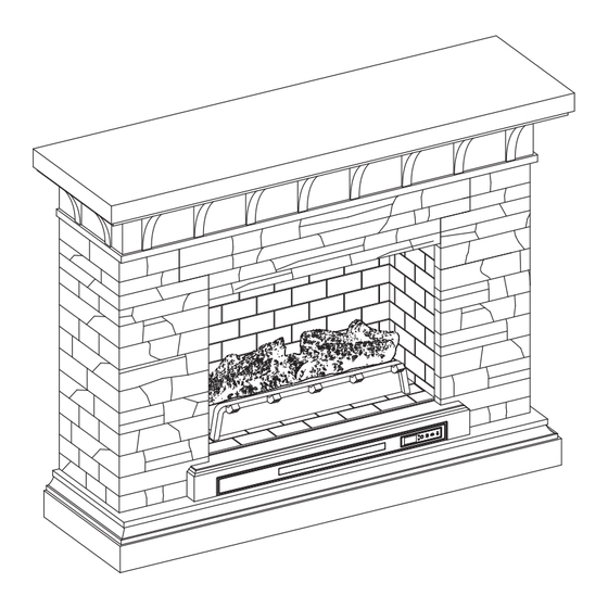
MODEL #2289SFP-53-26-934
53-IN ELECTRIC
ATTACH YOUR RECEIPT HERE
ascs@lowes.com.
1
ITEM #5703821
FIREPLACE
Español p. 21
Advertisement

Related Manuals for LF Allen + Roth 2289SFP-53-26-934


Summary of Contents for LF Allen + Roth 2289SFP-53-26-934
- Page 1 ITEM #5703821 MODEL #2289SFP-53-26-934 53-IN ELECTRIC ALLEN + ROTH and logo design are trademarks or registered trademarks of LF, LLC. All rights reserved. FIREPLACE Español p. 21 ATTACH YOUR RECEIPT HERE Serial Number__________________ Purchase Date__________________ Thank you for purchasing this ALLEN + ROTH product.
- Page 2 TABLE OF CONTENTS Package Contents ..........................3 Hardware Contents..........................4 Safety Information ..........................4 Preparation ............................8 Assembly Instructions.......................... 8 Operating Instructions ........................15 Care And Maintenance ........................17 Troubleshooting ..........................18 One-Year Limited Warranty ....................... 19 Replacement Parts List ........................20...
- Page 3 PACKAGE CONTENTS PART DESCRIPTION QUANTITY PART DESCRIPTION QUANTITY Base Panel and Heater Center Front Panel Front Trim Left Wall Base Right Wall Support Leg Firebox Top Panel Fire Log Fireplace Brick Wall Fireplace Grate Fireplace Glass Front Remote Control (Battery)
- Page 4 HARDWARE CONTENTS (NOT SHOWN ACTUAL SIZE) PART DESCRIPTION QUANTITY Long Bolt Screw Touch-up Pen Tip Restraint Hardware SAFETY INFORMATION Please read and understand this entire manual before • Reorient or relocate the receiving antenna. attempting to assemble, operate or install the product. •...
- Page 5 SAFETY INFORMATION (CONTINUED) • DO NOT insert or allow foreign objects to enter any Modifications not approved by the party responsible ventilation or exhaust opening as this may cause for compliance could void user’s authority to operate the equipment. an electric shock or fire or damage the appliance. •...
- Page 6 SAFETY INFORMATION (CONTINUED) • To avoid electric shock, fire, or injury, review the • To disconnect this appliance, turn controls to the assembly instruction to confirm that the appropriate OFF position, then remove plug from outlet. critical components and accessories are being used •...
- Page 7 SAFETY INFORMATION (CONTINUED) Electrical Connection Grounding Instructions • A 15-Amp, 120-volt, 60 Hz circuit with a properly • This heater is for use on 120-volt. The cord has a grounded outlet is required. Preferably, the plug as shown below. See illustration or grounding fireplace will be on a dedicated circuit as other instruction.
- Page 8 PREPARATION Before beginning assembly of product, make sure all parts are present. Compare parts with package contents list and hardware contents list. If any part is missing or damaged, do not attempt to assemble the product. Estimated Assembly Time: 30 minutes Tools Required for Assembly (not included): Phillips screwdriver ASSEMBLY INSTRUCTIONS...
- Page 9 ASSEMBLY INSTRUCTIONS (CONTINUED) 2. Carefully position the center front panel (B) into the space between the left wall (C) and right wall (D). Fasten long bolts (AA) on each side. Hardware Used Long Bolt 3. Place the front trim (I) onto the base (J), secure with two long bolts (AA).
- Page 10 ASSEMBLY INSTRUCTIONS (CONTINUED) 4. Attach the support leg (K) to the base panel and heater (H). Secure with screwing long bolt (AA) by Phillips screwdriver. Hardware Used Long Bolt 5. Place the base panel and heater (H) onto the base (J),fasten with two long bolts (AA). Hardware Used Long Bolt...
- Page 11 ASSEMBLY INSTRUCTIONS (CONTINUED) 6. Attach the top (A), fastening from underneath with two long bolts (AA). Hardware Used Long Bolt 7. From behind the mantel, attach the fireplace glass front (G), lowering it into the front groove on the base panel and heater (H). Secure the glass by turning the pre-assembled plastic knobs.
- Page 12 ASSEMBLY INSTRUCTIONS (CONTINUED) 8. Place the fireplace grate (N) by matching the bottom pins into the holes on the base panel and heater (H). Slot the USB cable from the heater underneath through the cable hole on the base panel and heater (H).
- Page 13 ASSEMBLY INSTRUCTIONS (CONTINUED) 10. Unfold the fireplace brick wall (F) and brackets. 11. Insert the fireplace brick wall (F) into the mantel, slotting it into the grooves on base panel and heater (H). Fasten the brackets to the back side of the right and left walls (D, C) using two screws (BB) into the bracket.
- Page 14 ASSEMBLY INSTRUCTIONS (CONTINUED) 12. Place the firebox top (E) on top of firebox panel with corner bumpers facing inward. WARNING: You must install the tip restraint (iii) hardware to help prevent any accidents or damage to the unit. We strongly recommend attaching the tip Wall Stud restraint hardware to a wall stud and your unit.
- Page 15 OPERATING INSTRUCTIONS Control Panel Remote Control To use the remote control, first insert two AAA batteries (included) into the remote control. Ensure the polarities of the batteries match the inside of the battery compartment. Controls and Display The control panel will display the heater setting when the unit power is turned ON. Whichever control icon you press will display the current setting of the corresponding function.
- Page 16 OPERATING INSTRUCTIONS (CONTINUED) Heater Function (Control Panel Only) • Press the HEATER ICON to display the current heater setting. • Press the HEATER ICON again to scroll down through the heater settings. Note: Long-hold the icon to quickly scroll through settings. •...
- Page 17 CARE AND MAINTENANCE • Make sure the unit is turned OFF, unplugged and the heating elements of heater are cool whenever you are cleaning the heater or fireplace. • Clean the metal trim using a water-dampened soft, clean cloth. DO NOT use brass polish or household cleaners as these products will damage the metal trim.
- Page 18 TROUBLESHOOTING PROBLEM POSSIBLE CAUSE CORRECTIVE ACTION Error E1 displayed on The overheat sensor has Unplug unit, wait 15-20 minutes, then the sensor will reset control panel. been engaged. itself. Plug the unit back in and turn on the heater. If the problem persists, call customer service.
- Page 19 ONE-YEAR LIMITED WARRANTY The manufacturer warrants that your new electric fireplace is free from manufacturing and material defects for a period of one year from date of purchase, subject to the following conditions and limitations. Install and operate this electric fireplace in accordance with the installation and operating instructions furnished with the product at all times.
- Page 20 REPLACEMENT PARTS LIST For replacement parts, call our customer service department at 8 6 6 - 4 3 9 - 9 8 0 0 8 a.m. - 8 p.m., EST, Monday - Sunday. You could also contact us at ascs@lowes.co PART DESCRIPTION PART #...
- Page 21 ARTÍCULO #5703821 MODELO #2289SFP-53-26-934 ALLEN + ROTH y el diseño del logotipo son 134.62 CM CHIMENEA marcas comerciales o marcas registradas de LF, LLC. Todos los derechos reservados. ELÉCTRICA ADJUNTE SU RECIBO AQUÍ Número de serie__________________ Fecha de compra__________________ Gracias por comprar este producto ALLEN+ROTH.
- Page 22 ÍNDICE Contenido del paquete ........................23 Aditamentos............................24 Información de seguridad ........................24 Preparación ............................28 Instrucciones de ensamblaje ......................28 Instrucciones de funcionamiento ....................... 35 Cuidado y mantenimiento ........................37 Solución de problemas ........................38 Garantía limitada de un año ......................39 Lista de piezas de repuesto.......................
- Page 23 CONTENIDO DEL PAQUETE PIEZA DESCRIPCIÓN CANTIDAD PIEZA DESCRIPCIÓN CANTIDAD Parte superior Panel de la base y Panel frontal central calentador Reborde frontal Pared izquierda Pared derecha Base Pata de soporte Panel superior de la cámara de combustión Leño para chimenea Pared de ladrillos de la Rejilla para chimenea chimenea...
- Page 24 ADITAMENTOS (NO SE MUESTRAN EN TAMAÑO REAL) PIEZA DESCRIPCIÓN CANTIDAD Perno largo Tornillo Aplicador de retoque Aditamento de contención antivuelcos INFORMACIÓN DE SEGURIDAD Lea y comprenda completamente este manual antes • Reorientar o reubicar la antena de recepción. de intentar ensamblar, usar o instalar el producto. •...
- Page 25 INFORMACIÓN DE SEGURIDAD (CONTINUACIÓN) • NO pase el cable debajo de muebles o Las modificaciones que no estén aprobadas por la electrodomésticos. Coloque el cable lejos de zonas parte responsable del cumplimiento podrían anular la autorización del usuario para utilizar el equipo. de tránsito donde nadie se pueda tropezar y caer.
- Page 26 INFORMACIÓN DE SEGURIDAD (CONTINUACIÓN) • Cada superficie prevista para soportar una carga • “ADVERTENCIA: la colocación de equipos de audio debe tener una declaración correspondiente en las y/o video en muebles no diseñados específicamente instrucciones de uso que indica la carga máxima en para soportar tales equipos puede causar la muerte kilogramos (libras) prevista para esa superficie.
- Page 27 INFORMACIÓN DE SEGURIDAD (CONTINUACIÓN) Conexión eléctrica Instrucciones de puesta a tierra • Se requiere un circuito de 15 amperios, 120 voltios, • Este calentador se diseñó para usarse con 60 Hz con un tomacorriente con la debida puesta 120 voltios. El cable tiene un enchufe como se a tierra.
- Page 28 PREPARACIÓN Antes de empezar a ensamblar el producto, asegúrese de que todas las piezas estén presentes. Compare las piezas con la lista del contenido del paquete y de los aditamentos. No intente ensamblar, instalar o usar el producto si faltan piezas o si están dañadas. Tiempo estimado de ensamblaje: 30 minutos Herramientas necesarias para el...
- Page 29 INSTRUCCIONES DE ENSAMBLAJE (CONTINUACIÓN) 2. Coloque con cuidado el panel frontal central (B) en el espacio entre la pared izquierda (C) y la pared derecha (D). Apriete los pernos largos (AA) en cada lado. Aditamentos utilizados Perno largo 3. Coloque el reborde frontal (I) sobre la base (J) y asegúrela con dos pernos largos (AA).
- Page 30 INSTRUCCIONES DE ENSAMBLAJE (CONTINUACIÓN) 4. Fije la pata de soporte (K) al panel base y al calentador (H). Asegúrela con un perno largo (AA) y utilice un destornillador Phillips. Aditamentos utilizados Perno largo 5. Coloque el panel base y al calentador (H) sobre la base (J) yapriételo con dos pernos largos (AA).
- Page 31 INSTRUCCIONES DE ENSAMBLAJE (CONTINUACIÓN) 6. Coloque la parte superior (A) y fíjela desde abajo con dos pernos largos (AA). Aditamentos utilizados Perno largo 7. Desde detrás de la repisa para chimenea, coloque el vidrio frontal de la chimenea (G), bajándolo en la ranura frontal del panel base y al calentador (H).
- Page 32 INSTRUCCIONES DE ENSAMBLAJE (CONTINUACIÓN) 8. Coloque la rejilla de la chimenea (N) haciendo coincidir los pasadores inferiores en los orificios del panel base y al calentador (H). Pase el cable USB del calentador por debajo a través del orificio para cable en el panel base y al calentador (H).
- Page 33 INSTRUCCIONES DE ENSAMBLAJE (CONTINUACIÓN) 10. Despliegue la pared de ladrillos de la chimenea (F) y los soportes. 11. Inserte la pared de ladrillos de la chimenea (F) en la repisa para chimenea, encajándola en las ranuras del panel base y alcalentador (H). Fije los soportes a la parte posterior de las paredes derecha eizquierda (D, C) con dos tornillos (BB) en elsoporte.
- Page 34 INSTRUCCIONES DE ENSAMBLAJE (CONTINUACIÓN) 12. Coloque el panel superior de la cámara de combustión (E) en la parte superior de la cámara de combustión con los protectores de esquina mirando hacia adentro. Advertencia: debe instalar el aditamento de (iii) contención antivuelcos para ayudar a evitar Montante de accidentes o daños a la unidad.
- Page 35 INSTRUCCIONES DE FUNCIONAMIENTO Panel de control Control remoto Para usar el control remoto, primero coloque dos baterías AAA (incluidas) en el control remoto. Asegúrese de que los polos de la batería coincidan dentro del compartimiento de baterías. Controles y pantalla El panel de control mostrará...
- Page 36 INSTRUCCIONES DE FUNCIONAMIENTO (CONTINUACIÓN) Función de calentador (solo panel de control) • Presione el ÍCONO DE CALENTADOR para mostrar la configuración actual del calentador. • Presione el ÍCONO DE CALENTADOR nuevamente para desplazarse hacia abajo a través de la configuración del calentador. Nota: mantenga presionado el ícono para desplazarse rápidamente por la configuración.
- Page 37 CUIDADO Y MANTENIMIENTO • Asegúrese de que la unidad esté APAGADA, desenchufada y que los elementos de calefacción estén fríos cada vez que limpie el calentador o la chimenea. • Limpie el borde metálico con un paño suave y limpio humedecido con agua. NO use pulidores de latón ni limpiadores domésticos, ya que estos productos dañarán el borde metálico.
- Page 38 SOLUCIÓN DE PROBLEMAS PROBLEMA CAUSA POSIBLE ACCIÓN CORRECTIVA El error E1 se muestra Se ha activado el sensor Desenchufe la unidad, espere de 15 a 20 minutos, luego el en el panel de control. de sobrecalentamiento. sensor se reiniciará automáticamente. Vuelva a enchufar la unidad y encienda el calentador.
- Page 39 GARANTÍA LIMITADA DE UN AÑO El fabricante garantiza que su nueva chimenea eléctrica no presentará defectos de fabricación ni en los materiales durante un período de un año a partir de la fecha de compra, siempre y cuando se cumplan las siguientes condiciones y limitaciones. Instale y use el la chimenea eléctrica según lo indican las instrucciones de instalación y funcionamiento provistas con el producto en todo momento.
- Page 40 LISTA DE PIEZAS DE REPUESTO Para obtener piezas de repuesto, llame a nuestro Departamento de Servicio al Cliente al , de lunes a domingo de 8 a.m. a 8 p.m., hora estándar del Este. También puede 866-439-9800 ponerse en contacto con nosotros en ascs@lowes.com.
Need help?
Do you have a question about the Allen + Roth 2289SFP-53-26-934 and is the answer not in the manual?
Questions and answers