Advertisement
Available languages
Available languages
Quick Links
MASTER FORGE and logo design are
trademarks or registered trademarks of LF,
LLC. All rights reserved.
Serial Number
Purchase Date
INSTALLER: Leave this manual with the appliance.
CONSUMER: Retain this manual for future reference.
WARNING: This appliance is equipped for (Natural and Propane) gas. Field conversion is not
permitted other than between natural or propane gases.
Thank you for purchasing this MASTER FORGE product.
Questions, problems or missing parts?
Before returning, contact us on:
1-877-447-4768, 8:30 a.m. - 4:30 p.m., CST, Monday - Friday or customerservice@ghpgroupinc.com.
SG24116
MODEL #VFL3-EO18DTL/VFL3-RW24DTL
GAS LOG SET
ATTACH YOUR RECEIPT HERE
1
ITEM #4976295/4976272
VENT-FREE
Español p. 39
Patent Pending
Dual Fuel System
NG
LP
Dual Fuel
C
US
C
C
US
ANS Z21.11.2
2019
IM80-10-442 - 2024-03-19
US
Advertisement

Subscribe to Our Youtube Channel
Related Manuals for LF MASTER FORGE VFL3-EO18DTL


Summary of Contents for LF MASTER FORGE VFL3-EO18DTL
- Page 1 ITEM #4976295/4976272 MODEL #VFL3-EO18DTL/VFL3-RW24DTL VENT-FREE GAS LOG SET MASTER FORGE and logo design are Español p. 39 trademarks or registered trademarks of LF, LLC. All rights reserved. ATTACH YOUR RECEIPT HERE Patent Pending Dual Fuel System Dual Fuel Serial Number ANS Z21.11.2...
- Page 2 TABLE OF CONTENTS Product Specifications ........................2 Safety Information ..........................3 Package Contents ..........................6 Product Features ..........................7 Preparing for Installation........................8 Installation ............................11 Assembly Instructions........................22 Operating Instructions ........................28 Care and Maintenance ........................32 Troubleshooting ..........................32 Warranty ............................
- Page 3 SAFETY INFORMATION CAUTION - FOR YOUR SAFETY WARNING: IF THE INFORMATION IN THIS MANUAL IS NOT FOLLOWED EXACTLY, A FIRE OR EXPLOSION MAY RESULT CAUSING PROPERTY DAMAGE, PERSONAL INJURY OR LOSS OF LIFE. - Do not store or use gasoline or other flammable vapors and Iiquids in vicinity of this or any other appliance.
- Page 4 SAFETY INFORMATION IMPORTANT: Read this owner’s manual carefully and completely before trying to assemble, operate, or service this heater. Improper use of this heater can cause serious injury or death from burns, fire, explosion, electrical shock, and carbon monoxide poisoning. WARNING: FIRE, EXPLOSION, AND ASPHYXIATION HAZARD Improper adjustment, alteration, service, maintenance, or installation of this heater or its controls can cause death or serious injury.
- Page 5 SAFETY INFORMATION WARNING This product and the fuels used to operate this product (liquid propane or natural gas), and the products of combustion of such fuels, can expose you to chemicals including benzene, which is known to the State of California to cause cancer and birth defects or other reproductive harm. For more information go to www.p65Warnings.ca.gov.
- Page 6 PACKAGE CONTENTS PART DESCRIPTION QUANTITY Grate Cap Battery Ignitor Thermostatic Control Valve Grate Log Locator Pins NG ODS Pilot LP ODS Pilot Burner Tube...
- Page 7 PRODUCT FEATURES This log set has been tested and approved to ANS Z21.11.2 2019 standard for Unvented Heaters and can be operated with the flue damper closed. State and local codes in some areas prohibit the use of vent-free heaters. DUAL FUEL CAPABILITY Your heater is equipped to operate on either propane or natural gas.
- Page 8 PREPARING FOR INSTALLATION WATER VAPOR: A BY-PRODUCT OF UNVENTED ROOM HEATERS Water vapor is a by-product of gas combustion. An unvented room heater produces approximately one (1) ounce (30 mL) of water for every 1,000 BTUs (.3 kw) of gas input per hour. An unvented room heater is recommended as a supplemental heater (a room) rather than a primary heat source (an entire house).
- Page 9 PREPARING FOR INSTALLATION DETERMINING FRESH-AIR FLOW FOR HEATER LOCATION Determining if You Have a Confined or Unconfined Space Use this worksheet to determine if you have a confined or unconfined space. Space: Includes the room in which you will install heater plus any adjoining rooms with doorless passageways or ventilation grills between the rooms.
- Page 10 PREPARING FOR INSTALLATION WARNING: If the area in which the heater may be operated does not meet the required volume for indoor combustion air, combustion and ventilation air shall be provided by one of the methods described in the NATIONAL FUEL GAS CODE, ANSI Z223.1/NFPA 54, the INTERNATIONAL FUEL GAS CODE, or applicable local codes.
- Page 11 INSTALLATION NOTICE: This heater is intended for use as supplemental heat. Use this heater along with your primary heating system. Do not install this heater as your primary heat source. If you have a central heating system, you may run system’s circulating blower while using heater. This will help circulate the heat throughout the house.
- Page 12 INSTALLATION CHECK GAS TYPE Make sure your gas supply is correct for your log set. If supply is not correct, do not install heater. Call dealer where you purchased heater for proper gas log set. LOG SIZING REQUIREMENTS Log Size Minimum Firebox Size Height Depth...
- Page 13 INSTALLATION MINIMUM NONCOMBUSTIBLE MATERIAL CLEARANCE (If Not Using Mantel) You must have noncombustible material(s) above the fireplace opening. Noncombustible materials (such as slate, marble, tile, etc.) must be at least 1/2 in. thick. With sheet metal, you must have noncombustible material behind it, such as a noncombustible fireplace hood accessory.
- Page 14 INSTALLATION MANTEL CLEARANCES In addition to meeting noncombustible material clearances, you must also meet required clearances between fireplace opening and mantel shelf. If the clearances listed below are not met, you will need to raise the mantel. Determining Mantel Clearances If you meet minimum clearance requirements between mantel shelf and top of fireplace opening, your installation (see Fig.
- Page 15 INSTALLATION FLOOR CLEARANCES a) If installing appliance on floor level, you must maintain the minimum distance of 14 in. to combustibles (see Fig. 8). b) If combustible materials are less than 14 in. to the fireplace, you must install appliance at least 5 in.
- Page 16 INSTALLATION WARNING: Failure to position the parts in accordance with these diagrams or failure to use only parts specifically approved with this heater may result in property damage or personal injury. Before beginning assembly or operation of the product, make sure all parts are present. Compare parts with package contents list.
- Page 17 INSTALLATION GAS SELECTION INSTRUCTIONS WARNING: This appliance can be used with propane or natural gas. It is shipped from the factory adjusted for use with propane. CAUTION: The knob to the gas selection means shall not be accessed or adjusted while the appliance is in operation.
- Page 18 INSTALLATION CONNECTING TO GAS SUPPLY WARNING: A qualified service technician must connect heater to gas supply. Follow all local codes. CAUTION: Never connect heater directly to the gas supply. This heater requires an external regulator (not supplied). The external regulator between the gas supply and heater must be installed. Gas supplier provides external regulator for natural gas.
- Page 19 INSTALLATION CAUTION: Use pipe joint sealant that is resistant to gas (PROPANE or NG). We recommend that you install a sediment trap in a supply line. Locate sediment trap where it is within reach for cleaning and not likely to freeze. Install in the piping system between fuel supply and heater. A sediment trap traps moisture and contaminants.
- Page 20 INSTALLATION CHECKING GAS CONNECTIONS WARNING: Test all gas piping and connections for leaks after installing or servicing. Correct all leaks immediately. WARNING: Never use an open flame to check for a leak. Apply a mixture of liquid soap and water to all joints.
- Page 21 INSTALLATION BEFORE INSTALLING THE APPLIANCE - Turn off gas supply to fireplace or firebox. - Clean fireplace floor and chimney before installing log set. Seal any ash. Clean outdoors to protect the unit from down drafts. MOUNTING PROCEDURE - Place grate/burner assembly into firebox with the front pan facing forward. - Drill two (2) 5/32”...
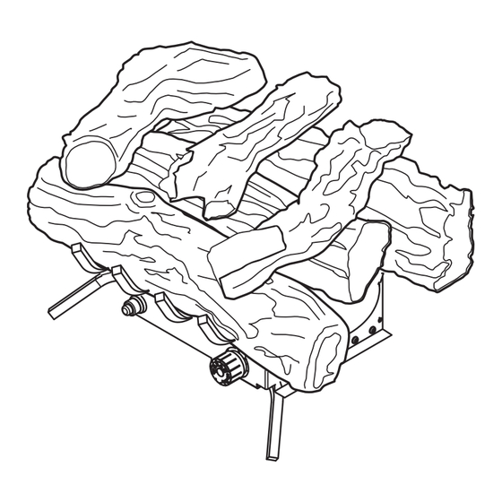
- Page 22 ASSEMBLY INSTRUCTIONS 4976295 /VFL3-EO18DTL WARNING: Failure to position the parts in accordance with these diagrams or failure to use only parts specifically approved with this heater may result in property damage or personal injury. CAUTION: After installation and periodically thereafter, check to ensure that no yellow flame comes in contact with any log.
- Page 23 ASSEMBLY INSTRUCTIONS 4976295 /VFL3-EO18DTL 3. Place log #3 onto the front grate. Make sure the recessed areas on the log match up with the grate, and the log is centered on grate. 4. Place log #4 so its pin fits into the hole on the top left recessed areas of log #2.
- Page 24 ASSEMBLY INSTRUCTIONS 4976295 /VFL3-EO18DTL 5. Place log #5 so it is resting in the top middle recessed areas of log #1 and its pin fits in the hole on the top of log #2 only (it should NOT be touching log #3), and the front edge does not over hang log #2.
- Page 25 ASSEMBLY INSTRUCTIONS 4976272 /VFL3-RW24DTL WARNING: Failure to position the parts in accordance with these diagrams or failure to use only parts specifically approved with this heater may result in property damage or personal injury. CAUTION: After installation and periodically thereafter, check to ensure that no yellow flame comes in contact with any log.
- Page 26 ASSEMBLY INSTRUCTIONS 4976272 /VFL3-RW24DTL 3. Place log #3 & log #4 onto the front grate. Make sure the recessed areas on the logs match up with the grate, and the logs are centered on grate. 4. Place log #5 so its pin fits into the hole on the top left recessed areas of log #2.
- Page 27 ASSEMBLY INSTRUCTIONS 4976272 /VFL3-RW24DTL 5. Place log #6 so it is resting in the top middle recessed areas of log #1 and its pin fits in the hole on the top of log #2. 6. Place log #7 so its pin fits in the hole on the topright recessed areas of log #2.
- Page 28 OPERATING INSTRUCTIONS FOR YOUR SAFETY READ BEFORE LIGHTING WARNING: If you do not follow these instructions exactly, a fire or explosion may result causing property damage, personal injury or loss of life. A. This appliance has a pilot which must be lighted by the electronic ignitor. When lighting the pilot, follow these instructions exactly.
- Page 29 OPERATING INSTRUCTIONS LIGHTING INSTRUCTIONS 1. STOP! Read the safety information above. 2. Turn control knob clockwise to the “OFF” position (See Fig. 21). 3. Wait five (5) minutes to clear out any gas. Then smell for gas, in- cluding near the floor. If you smell gas, STOP! Follow “B” in the safety information above.
- Page 30 OPERATING INSTRUCTIONS INSPECTING BURNERS Check pilot flame pattern and burner flame patterns often. PILOT FLAME PATTERN Figure 23 shows a correct pilot flame pattern. Figure 24 shows an incorrect pilot flame pattern. The incorrect pilot flame is not touching the thermocouple. This will cause the thermocouple to cool. When the thermocouple cools, the heater will shut down.
- Page 31 OPERATING INSTRUCTIONS BURNER FLAME PATTERN Figure 25 shows a correct burner flame pattern. Figure 26 shows an incorrect burner flame pattern. The incorrect burner flame pattern shows sporadic, irregular flame tipping. The flame should not be dark or have an orange/reddish tinge. Note: When using the heater for the first time, the flame will be orange for approximately one hour until the log cures.
- Page 32 CARE AND MAINTENANCE 1. Shut off unit including pilot. Allow unit to cool for at least 30 minutes. 2. Inspect burner, pilot and primary air inlet holes on orifice holder for dust and dirt (See Fig. 27). 3. Blow air through the ports/slots and holes in the burner. 4.
- Page 33 WARNING: Make sure that power is turned off before proceeding. WARNING: Turn off and let cool before servicing. Only a qualified service person should service and repair heater. CAUTION: Never use a wire, needle, or similar object to clean ODS/pilot. This can damage ODS/ pilot unit.
- Page 34 TROUBLESHOOTING PROBLEM POSSIBLE CAUSE CORRECTIVE ACTION ODS/pilot lights 1. Control knob is not fully 1. Press in control knob fully. but flame goes out pressed in. 2. After ODS/pilot lights, keep when control knob is 2. Control knob is not pressed in control knob pressed in 30 released.
- Page 35 TROUBLESHOOTING PROBLEM POSSIBLE CAUSE CORRECTIVE ACTION White powder residue 1. When heated, the vapors from 1. Turn heater off when using forming within burner furniture polish, wax, carpet furniture polish, wax, carpet box or on adjacent cleaners, etc., turn into white cleaner or similar products.
- Page 36 WARRANTY LIMITED WARRANTY This limited warranty is extended to the original retail purchaser of this heater and warrants against any defect in materials and workmanship for a period of two (2) years from the date of retail sale. GHP Group, Inc., at it’s option, will either provide replacement parts or replace or repair the unit, when prop- erly returned to the retailer where purchased or one of our service centers as directed by GHP Group, Inc., within two (2) years of retail purchase.
- Page 37 REPLACEMENT PARTS LIST For replacement parts, call our Technical Service Department at 1-877-447-4768, 8:30 a.m. - 4:30 p.m., CST, Monday – Friday. 4976295/ VFL3-EO18D- 4976272/ VFL3- RW24DTL PART NO. ITEM NO. DESCRIPTION 4976295 /VFL3-EO18DTL 4976272 /VFL3-RW24DTL Log Set (complete) 3DYDA18 3DYDA18 Log 1 80-06-168...
- Page 38 REPLACEMENT PARTS LIST PART NO. ITEM NO. DESCRIPTION 4976295 /VFL3-EO18DTL 4976272 /VFL3-RW24DTL ODS Pilot - LP GZ20-17 GZ20-17 Selector Knob GR-130B-GHP GR-130B-GHP Regulator, NG 5” WC GR-130A-GHP GR-130A-GHP Regulator, LP 10” WC GZ20-32a GZ20-32a Control Valve, Euro SIT 630 0630560 0630560 Printed in China...
- Page 39 A GAS SIN VENTILACIÓN English p. 1 MASTER FORGE y el diseño del logotipo son marcas comerciales o marcas registradas ADJUNTE SU RECIBO AQUÍ de LF, LLC. Todos los derechos eservados. Sistema de combustible doble con patente en trámite Doble combustible Número de serie...
- Page 40 ÍNDICE Especificaciones ..........................40 Información de seguridad ....................... 41 Contenido del paquete ........................45 Características del producto ......................46 Preparación para la instalación ...................... 47 Instalación ............................50 Instrucciones de ensamblaje ......................61 Funcionamiento ..........................67 Cuidado y mantenimiento ....................... 70 Solución de problemas ........................
- Page 41 INFORMACIÓN DE SEGURIDAD PRECAUCIÓN: PARA SU SEGURIDAD ADVERTENCIA: SI NO SE SIGUE CON PRECISIÓN LA INFORMACIÓN DE ESTE MANUAL, SE PODRÍA PRODUCIR INCENDIOS O EXPLOSIONES QUE RESULTEN EN DAÑOS MATERIALES, LESIONES PERSONALES O LA MUERTE. - No almacene ni utilice gasolina ni otros vapores o líquidos inflamables cerca de este o cualquier otro electrodoméstico.
- Page 42 INFORMACIÓN DE SEGURIDAD ADVERTENCIA: no intente acceder o cambiar la configuración de los medios de selección de combustible. El acceso y ajuste de los medios de selección de combus- tible solo debe estar a cargo de una persona de servicio calificada en el momento de conectar este electrodoméstico a un suministro de combustible especificado durante la instalación.
- Page 43 INFORMACIÓN DE SEGURIDAD ADVERTENCIA: - Debido a las altas temperaturas, coloque el aparato fuera de las zonas por donde se tran- sita y lejos de muebles y cortinas. - El calentador alcanza temperaturas muy altas cuando está en funcionamiento. Mantenga a los niños y los adultos lejos de las superficies calientes para evitar quemaduras o que la ropa se encienda.
- Page 44 INFORMACIÓN DE SEGURIDAD 8. Para evitar que se produzca hollín, siga las instrucciones de Cuidado y mantenimiento, páginas 68 a 69. 9. Apague el calentador antes de utilizar pulidor para muebles, cera, productos de limpieza para alfombras o productos similares. Si se calientan, los vapores de estos productos pueden producir un residuo en forma de polvo blanco dentro de la caja del quemador o en las paredes y muebles cercanos.
- Page 45 CONTENIDO DEL PAQUETE ARTÍCULO DESCRIPCIÓN Tapa de rejilla Encendedor a batería Válvula de control termostática Rajilla Pasadores de fijación de los leños Piloto ODS de GN Piloto ODS de PL Tubo quemador...
- Page 46 CARACTERÍSTICAS DEL PRODUCTO Este juego de leños está probado y aprobado por la Norma ANS Z21.11.2 2019 para los calentadores sin ventilación y se puede usar con el regulador de tiro cerrado. Los códigos locales y estatales de algunas áreas prohíben el uso de calentadores de tiro natural. CAPACIDAD DE COMBUSTIBLE DOBLE El calentador está...
- Page 47 PREPARACIÓN PARA LA INSTALACIÓN VAPOR DE AGUA: UN PRODUCTO DERIVADO DE LOS CALENTADORES DE HABITACIÓN SIN VENTILACIÓN VENTILACIÓN El vapor de agua es un producto derivado de la combustión de gas. Un calentador de habitación sin ventilación produce aproximadamente 29,57 ml (1 onza) de agua por cada 1000 BTU (0,29 kW) de entrada de gas por hora.
- Page 48 PREPARACIÓN PARA LA INSTALACIÓN b) posee burletes en las ventanas que se pueden abrir y en las puertas; y c) se le ha aplicado masilla de calafateo o sellador a áreas como las juntas alrededor de las ventanas y los marcos para puertas, entre los largueros de solera y el piso, en las juntas de pared y techo, entre los paneles, en los orificios de las líneas de plomería, eléctricas y de gas, y en otras aberturas.
- Page 49 PREPARACIÓN PARA LA INSTALACIÓN ADVERTENCIA: si el área en la que funcionará el calentador no cumple con el volumen requerido de aire de combustión en interiores, se debe proporcionar aire de ventilación y combustión por medio de uno de los métodos que se describen en el CÓDIGO NACION- AL DE GAS COMBUSTIBLE, ANSI Z223.1/NFPA 54, el CÓDIGO INTERNACIONAL DE GAS COMBUSTIBLE o los códigos locales correspondientes.
- Page 50 INSTALACIÓN AVISO: este calentador está diseñado para su uso como calefacción suplementaria. Utilice este calentador junto con su sistema de calefacción principal. No instale este calentador como fuente principal de calefacción. Si posee un sistema de calefacción centralizada, puede encender el soplador de circulación del sistema mientras usa el calentador.
- Page 51 INSTALACIÓN VERIFIQUE EL TIPO DE GAS Asegúrese de que el suministro de gas sea el adecuado para el juego de leños. Si el suministro no es el adecuado, no instale el calentador. Comuníquese con el distribuidor donde lo adquirió para obtener el juego de leños simulados a gas correcto.
- Page 52 INSTALACIÓN DISTANCIA DE SEPARACIÓN MÍNIMA PARA MATERIALES NO COMBUSTIBLES (Si no usa una repisa para chimenea) Debe tener material(es) no combustibles(s) sobre la abertura de la chimenea. Los materiales no combustibles (como pizarra, mármol, baldosa, etc.) deben tener un mínimo de 1,27 cm de espesor. Debe tener material no combustible detrás de la lámina de metal, tal como un accesorio de campana extractora no combustible para chimenea.
- Page 53 INSTALACIÓN DISTANCIAS DE SEPARACIÓN DE LAS REPISAS PARA CHIMENEA Además de encontrar las distancias de separación del material no combustible, debe encontrar las distancias de separación requeridas entre la abertura y la repisa para chimenea. Si no se cumplen las distancias de separación mencionadas a continuación, deberá elevar la repisa para chimenea. Determinación de las distancias de separación de las repisas para chimenea Si cumple con los requisitos de distancia de separación mínima entre la repisa para chimenea y la parte superior de la abertura de la chimenea, su instalación (consulte la Fig.
- Page 54 INSTALACIÓN DISTANCIAS DE SEPARACIÓN DEL PISO a) Si instala el electrodoméstico al nivel del piso, debe mantener la distancia mínima de 35,56 cm. de los combustibles (consulte la Fig. 8). b) Si los materiales combustibles están a menos de 35,56 cm. de la chimenea, debe instalar el electrodoméstico al menos a 12,7 cm.
- Page 55 INSTALACIÓN ADVERTENCIA: no colocar las piezas de acuerdo con estos diagramas o no usar solo las piezas aprobadas específicamente con este calentador puede ocasionar daños materiales o lesiones personales. Antes de comenzar a ensamblar u operar el producto, asegúrese de tener todas las piezas. Compare las piezas con la lista del contenido del paquete.
- Page 56 INSTALACIÓN INSTRUCCIONES DE SELECCIÓN DE GAS ADVERTENCIA: este electrodoméstico se puede usar con gas propano o gas natural. Se envía de fábrica configurado para usarse con propano. PRECAUCIÓN: la perilla del medio para seleccionar el combustible no debe manipularse ni regularse mientras que el electrodoméstico esté...
- Page 57 INSTALACIÓN CONEXIÓN AL SUMINISTRO DE GAS ADVERTENCIA: un técnico de mantenimiento calificado debe realizar la conexión del calentador al suministro de gas. Respete todos los códigos locales. PRECAUCIÓN: nunca conecte el calentador directamente al suministro de gas. Este calentador necesita un regulador externo (no incluido). Se debe instalar el regulador externo entre el suministro de gas y el calentador.
- Page 58 INSTALACIÓN PRECAUCIÓN: utilice sellador para juntas de tuberías que sea resistente al gas (PROPANO O GN) Recomendamos que instale una trampa para sedimentos en la línea de entrada. Coloque la trampa de sedimentos donde se pueda alcanzar para limpiarla y no sea probable que el material atrapado se congele.
- Page 59 INSTALACIÓN VERIFICACIÓN DE LAS CONEXIONES DE GAS ADVERTENCIA: verifique todas las tuberías y conexiones de gas para detectar fugas después de la instalación o el mantenimiento. Repare todas las fugas de inmediato. ADVERTENCIA: no use nunca una llama directa para detectar fugas. Aplique una mezcla de jabón líquido y agua en todas las juntas.
- Page 60 INSTALACIÓN ANTES DE INSTALAR EL ELECTRODOMÉSTICO - Cierre el suministro de gas a la chimenea o la cámara de combustión. - Limpie el piso de la chimenea y la chimenea antes de instalar el juego de leños. Selle toda la ceniza. Limpie el exterior para proteger la unidad de las corrientes de aire descendentes.
- Page 61 INSTRUCCIONES DE ENSAMBLAJE 4976295 /VFL3-EO18DTL ADVERTENCIA: no colocar las piezas de acuerdo con estos diagramas o no usar solo las piezas aprobadas específicamente con este calentador puede ocasionar daños materiales o lesiones personales. PRECAUCIÓN: después de la instalación y de forma periódica, compruebe que las llamas amaril- las no entren en contacto con los leños.
- Page 62 INSTRUCCIONES DE ENSAMBLAJE 4976295 /VFL3-EO18DTL 3. Coloque el leño n.° 3 en la rejilla delantera. Asegúrese de que las áreas empotradas en el leño coincidan con la rejilla y que el leño esté centrado en la rejilla. 4. Coloque el leño n.° 4 de modo que su pasador encaje en el orificio de las áreas empotradas superiores izquierdas del leño n.°...
- Page 63 INSTRUCCIONES DE ENSAMBLAJE 4976295 /VFL3-EO18DTL 5. Coloque el leño n.° 5 de manera que descanse en las áreas empotradas de la parte central superior del leño n.° 1 y su pasador encaje en el orificio de la parte superior del leño n.° 2 únicamente (NO debe tocar el leño n.°...
- Page 64 ASSEMBLY INSTRUCTIONS 4976272 /VFL3-RW24DTL ADVERTENCIA: no colocar las piezas de acuerdo con estos diagramas o no usar solo las piezas aprobadas específicamente con este calentador puede ocasionar daños materiales o lesiones personales. PRECAUCIÓN: después de la instalación y de forma periódica, compruebe que las llamas amaril- las no entren en contacto con los leños.
- Page 65 INSTRUCCIONES DE ENSAMBLAJE 4976272 /VFL3-RW24DTL 3. Coloque los leños n.° 3 y n.° 4 en la rejilla delantera. Asegúrese de que las áreas empotradas de los leños coincidan con la rejilla y que los leños estén centrados en la rejilla. 4.
- Page 66 INSTRUCCIONES DE ENSAMBLAJE 4976272 /VFL3-RW24DTL 5. Coloque el leño n.° 6 de modo que descanse en las áreas empotradas de la parte central superior del leño n.° 1 y su pasador encaje en el orificio en la parte superior del leño n.° 2. 6.
- Page 67 INSTRUCCIONES DE FUNCIONAMIENTO POR SU SEGURIDAD, LEA ANTES DE ENCENDER EL ELECTRODOMÉSTICO ADVERTENCIA: si no sigue con precisión estas instrucciones, podría provocar un incendio o una explosión que resulte en daños materiales, daños personales o muerte. A. Este electrodoméstico cuenta con un piloto que se debe encender por medio del encendedor electrónico.
- Page 68 INSTRUCCIONES DE FUNCIONAMIENTO INSTRUCCIONES DE ENCENDIDO 1. ¡DETÉNGASE! Lea la información de seguridad como se indicó anteriormente. 2. Gire la perilla de control en dirección de las manecillas del reloj hacia la posición OFF (apagado) (consulte la Fig. 21). 3. Espere cinco (5) minutos para que se despeje el gas. Luego verifique Fig.
- Page 69 INSTRUCCIONES DE FUNCIONAMIENTO INSPECCIÓN DE LOS QUEMADORES Revise frecuentemente el comportamiento de la llama del piloto y de la llama del quemador. COMPORTAMIENTO DE LA LLAMA DEL PILOTO La Fig. 23 muestra el comportamiento correcto de la llama del piloto. La Fig. 24 muestra el comportamiento incorrecto de la llama del piloto.
- Page 70 CUIDADO Y MANTENIMIENTO COMPORTAMIENTO DE LA LLAMA DEL QUEMADOR La figura 25 muestra el comportamiento correcto de la llama del quemador. La Fig. 26 muestra el comportamiento incorrecto de la llama del quemador. El comportamiento incorrecto de la llama del quemador muestra una inclinación esporádica e irregular de la llama.
- Page 71 CUIDADO Y MANTENIMIENTO 1. Apague la unidad, incluido el piloto. Deje enfriar la unidad durante al menos 30 minutos. 2. Compruebe que el quemador, el piloto y los orificios principales de entrada de aire del soporte del orificio no presenten polvo ni suciedad (consulte la Fig. 27). 3.
- Page 72 ADVERTENCIA: asegúrese de que la unidad esté apagada antes de proceder. ADVERTENCIA: apague el calentador y déjelo enfriar antes de cualquier repaarción. Solo un técnico calificado debe realizar el mantenimiento o reparar el calentador. PRECAUCIÓN: nunca utilice un alambre, una aguja o un objeto similar para limpiar el piloto/ODS. Pueden dañar la unidad del piloto/ODS.
- Page 73 SOLUCIÓN DE PROBLEMAS PROBLEMA CAUSA POSIBLE ACCIÓN CORRECTIVA Cuando se presiona el 1. El suministro de gas está 1. Abra el suministro de gas o la botón de encendido, cerrado o la válvula de cierre válvula de cierre del equipo. hay chispa en el piloto/ del equipo está...
- Page 74 SOLUCIÓN DE PROBLEMAS PROBLEMA CAUSA POSIBLE ACCIÓN CORRECTIVA El quemador no se 1. La presión de entrada de 1. Póngase en contacto con su enciende una vez gas es demasiado alta. proveedor de gas. encendido el piloto/ ODS. (El calentador está...
- Page 75 SOLUCIÓN DE PROBLEMAS PROBLEMA CAUSA POSIBLE ACCIÓN CORRECTIVA Se forman residuos 1. Al calentarse, los vapores de 1. Apague el calentador cuando en forma de polvo la cera para muebles, cera, utilice cera para muebles, blanco en la caja del productos de limpieza para cera, productos de limpieza quemador o en las...
- Page 76 SOLUCIÓN DE PROBLEMAS PROBLEMA CAUSA POSIBLE ACCIÓN CORRECTIVA El calentador produce 1. Se colocó la perilla de control 1. Coloque la perilla de control un silbido cuando en posición alta (5) con el en la posición baja (1) y el quemador está quemador frío.
- Page 77 WARRANTY GARANTÍA LIMITADA Esta garantía limitada se extiende al comprador minorista original de este calentador y cubre cual- quier defecto en los materiales y la mano de obra por un período de dos (2) años a partir de la fecha de venta minorista.
- Page 78 LISTA DE PIEZAS DE REPUESTO Para obtener piezas de repuesto, llame a nuestro Departamento de Servicio Técnico al 1-877-447- 4768 de lunes a viernes de 8:00 a.m. a 4:30 p.m., hora central estándar. 4976295/ VFL3-EO18DTL 4976272/ VFL3-RW24DTL PIEZA N.° ARTÍCULO DESCRIPCIÓN CANT.
- Page 79 LISTA DE PIEZAS DE REPUESTO PIEZA N.° ARTÍCULO DESCRIPCIÓN CANT. 4976295 /VFL3-EO18DTL 4976272 /VFL3-RW24DTL N.° Piloto ODS PL GZ20-29B GZ20-29B Perilla de selector GZ20-17 GZ20-17 Regulador, (GN) Gas GR-130B-GHP GR-130B-GHP Natural 5” W.C. Regulador, (PL) Propano GR-130A-GHP GR-130A-GHP Líquido 10”. Módulo del encendador GZ20-32a GZ20-32a...
Need help?
Do you have a question about the MASTER FORGE VFL3-EO18DTL and is the answer not in the manual?
Questions and answers