Table of Contents
Advertisement
Available languages
Available languages
ALLEN+ROTH and logo design are trademarks or
registered trademarks of LF, LLC.
All rights reserved.
Serial Number:
Questions, problems, missing parts? Before returning to your retailer,
call our customer service department at 866-439-9800, 8 a.m. - 8 p.m.,
EST, Monday - Sunday. You can also contact us at ascs@lowes.com.
AS24019
Purchase Date:
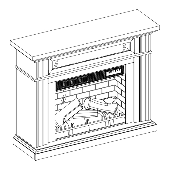
ELECTRIC FIREPLACE
MODEL # 149148 / 28WM373-TPF11
ITEM # 5228467
51 in
Español p. 34
Advertisement
Chapters
Table of Contents

Related Manuals for LF Allen + Roth 149148/28WM373-TPF11


Summary of Contents for LF Allen + Roth 149148/28WM373-TPF11
- Page 1 ITEM # 5228467 51 in ELECTRIC FIREPLACE ALLEN+ROTH and logo design are trademarks or registered trademarks of LF, LLC. All rights reserved. MODEL # 149148 / 28WM373-TPF11 Español p. 34 Serial Number: Purchase Date: Questions, problems, missing parts? Before returning to your retailer, call our customer service department at 866-439-9800, 8 a.m.
-
Page 2: Table Of Contents
TABLE OF CONTENTS Product Specifications ..........................2 Safety Information.............................3 Maximum Load............................Package Contents.............................6 Hardware Contents...........................8 Preparation.............................. Assembly Instructions..........................9 Operating Instructions..........................26 Troubleshooting............................. FCC/IC Information..........................29 Care and Maintenance..........................29 Warranty..............................Battery Replacement..........................31 Replacement Parts List......................... PRODUCT SPECIFICATIONS VOLTAGE 120VAC, 60 Hz AMPS 12.5 Amps WATTS 1500 Watts 28WM373 REV2.0... -
Page 3: Safety Information
SAFETY INFORMATION When using electrical appliances, basic precautions should always be followed to reduce the risk of fire, electrical shock, and injury to persons including the following: 1. Read all instructions before using this appliance. 2. DANGER – High temperatures may be generated under certain abnormal conditions. Do not partially or fully cover or obstruct the front of this heater. - Page 4 12. Do not insert or allow foreign objects to enter any ventilation or exhaust opening as this may cause an electric shock or fire, or damage the appliance. 13. To prevent a possible fire, do not block air intakes or exhaust in any manner. Do not use on soft surfaces, like a bed, where opening may become blocked.
-
Page 5: Maximum Load
MAXIMUM LOAD MAXIMUM LOAD 18.14 kg / 40 lb WARNING Loads heavier than the maximum weights specified may result in instability, causing tip over resulting in death or serious injury. 28WM373 REV2.0... -
Page 6: Package Contents
PACKAGE CONTENTS 28WM373 REV2.0... - Page 7 PACKAGE CONTENTS PART DESCRIPTION QUANTITY Bottom Panel Base Left Panel Base Back Panel Base Right Panel Base Front Panel Left Upper Front Panel Top Panel Left Upper Side Panel Left Upper Partition Right Upper Front Panel Right Upper Side Panel Right Upper Partition Flip Down Door Fixed Shelf...
-
Page 8: Hardware Contents
HARDWARE CONTENTS Plastic Connector Ø3x15mm Gas Spring Ø6.3x12mm Magnetic Catch Block Screw Bolt Qty: 4 Qty: 2 Qty: 53 Qty: 110 Qty: 2 Ø3.5x12mm Ø4x50mm Handle (with screws) Right Pin Hinge Left Pin Hinge Screw Screw Qty: 1 Qty: 1 Qty: 11 Qty: 1 Qty: 10... -
Page 9: Preparation
HARDWARE CONTENTS Wire Clip Qty: 3 PREPARATION Before beginning assembly of product, make sure all parts are present. Compare parts with package contents list and hardware contents list. If any part is missing or damaged, do not attempt to assemble, install or operate the product. To protect the product from possible scratches, please assemble the parts on a scratch-free surface. - Page 10 ASSEMBLY INSTRUCTIONS 2. Connecting the Bottom Rails • Attach Base Left Panel (B2) and Base Right Panel (D2) to the Base Back Panel (C) by inserting the Bolts (BB) through the Plastic Connector Blocks (AA). • Tighten with a Phillips screwdriver as shown. Hardware Used Ø6.3x12mm Bolt...
- Page 11 ASSEMBLY INSTRUCTIONS 5. Attaching the Door Catch • Locate the Top Panel (G2) and place on a flat surface. • Attach the Magnetic Door Catches (CC) to the Top Panel (G2) using Screws (DD) where indicated by the diagram. Note: Do not tighten the screws in this step. After assembling the door in step 36, adjust the position of the magnets forward or backward to better match the door to the unit, and then...
- Page 12 ASSEMBLY INSTRUCTIONS 8. Attaching the Gas Spring Side Mount Hardware • Attach the Side Mount hardware for the Gas Springs (EE) to the Left Upper Partition (I2) and the Right Upper Partition (L2), using screws (EE). Hardware Used Gas Spring Ø3.5x12mm Screw 9.
- Page 13 ASSEMBLY INSTRUCTIONS 11. Constructing the Side Partitions • Attach Left Upper Partition (I2) to Left Upper Front Panel (F2) using the Plastic Connector Blocks (AA) with Bolts (BB). • Repeat these steps to attach the Right Upper Partition (L2) to Right Upper Front Panel (J2). Hardware Used Ø6.3x12mm Bolt...
- Page 14 ASSEMBLY INSTRUCTIONS 14. Preparing the Flip Down Door • Continue preparing the Flip Down Door (M) by attaching the Bottom Mount Hardware for the Gas Springs (EE), using Screws (EE) as shown. Hardware Used Gas Spring Ø3.5x12mm Screw 15. Preparing the Flip Down Door •...
- Page 15 ASSEMBLY INSTRUCTIONS 17. Connecting Flip Down Door to the Left Upper Panel Assembly • Connect the Flip Down Door (M) to the Left Upper Panel Assembly by inserting the pin hinges into the predrilled holes in the side of Left Upper Panel Assembly.
- Page 16 ASSEMBLY INSTRUCTIONS 20. Aligning the Upper Back Panel • Align the Upper Back Panel (O) with the upper assembly attaching Screws (KK) to the corners first. Hardware Used Ø3x12mm Screw 21. Securing the Upper Back Panel • Attach the Upper Back Panel (O) to the upper assembly by securing all Screws (KK) with a Phillips screwdriver as shown.
- Page 17 ASSEMBLY INSTRUCTIONS 23. Preparing the Side Panels • Fasten each Plastic Connector Block (AA) using Bolts (BB) on the Left and Right Side Panels (Q2 and S2). Hardware Used Plastic Connector x 14 Block Ø6.3x12mm x 14 Bolt 24. Connecting the Panels •...
- Page 18 ASSEMBLY INSTRUCTIONS 26. Attaching the Wire Clips • Insert Wire Clips (UU) into pre-drilled holes in the rail of the Right Surround Panel (V2), pushing them in by hand. Hardware Used Wire Clips 27. Preparing the Surround Panels • Fasten each Plastic Connector Block (AA) using Bolts (BB) on the Left and Right Surround Panels (T2 and V2).
- Page 19 ASSEMBLY INSTRUCTIONS 29. Assembling the Fireplace • Locate the Front Panel with Control Button (EA). • Using Screws (FF), secure the Front Panel with Control Button (EA) inside the inner surround assembly as shown. Hardware Used Ø3.5x12mm Screw 30. Attach the front Fireplace Surround to the Main Assembly •...
- Page 20 ASSEMBLY INSTRUCTIONS 32. Placing the Glass Front • Locate the Front Glass Panel (W). • Carefully insert the Front Glass Panel (W) into the grooves of the surround rails as shown. Slide all the way in until the glass meets the bottom of the Control Support Panel.
- Page 21 ASSEMBLY INSTRUCTIONS 35. Attaching the Base • Align the predrilled holes in Bottom Panel (A2) with the hardware on the edges of the main assembly. • Secure the Bottom Panel to the main assembly by tightening the hardware with a Phillips screwdriver as shown.
- Page 22 ASSEMBLY INSTRUCTIONS 38. Assembling the Log Set • Place the Log Set Left (EJ) and Log Set Right (EK) into the Log Set Middle (EL) and Ember Bed (EI) as shown. 39. Assembling the Log Set • Route the wires of the Log Set Left (EJ) , the Log Set Right (EK) and Log Set Middle (EL) down the back of the Ember Bed (EI) and into the receiving tabs to secure in place.
- Page 23 ASSEMBLY INSTRUCTIONS 41. Securing the Log Set • Once the log set is in place, secure with Screws (FF) through the bottom of the log set and into the base. Hardware Used Ø3.5x12mm Screw 42. Connecting the Fireplace Wiring • Connect control panel cable to heater. •...
- Page 24 ASSEMBLY INSTRUCTIONS 44. Positioning the Fireplace Background • Position the Electric Fireplace Back Panel (X) behind the electric fireplace and center as shown. 45. Securing the Fireplace Background • Secure the Electric Fireplace Back Panel (X) to the Base with the Metal Brackets (PP) and Screws (QQ), as shown.
- Page 25 ASSEMBLY INSTRUCTIONS 46. Installing the Tip Restraint Hardware • When the Tipping Restraint Hardware (ZZ) is properly installed, it can provide protection against unexpected tipping of the Unit due to small tremors, bumps or climbing. • Each Tipping Restraint Hardware (ZZ) includes one Unit Anchor, one Wall Anchor, one Anchor Tether, and two Anchor Screws.
-
Page 26: Operating Instructions
OPERATING INSTRUCTIONS CONTROL PANEL LOCATION ICON DESCRIPTION FUNCTION The POWER button supplies power to all the functions of the heater. Pressing the POWER button again will put the heater in standby mode. POWER Holding the Power button on the control panel for 10 seconds will disable the heater function. - Page 27 OPERATING INSTRUCTIONS FUNCTION ICON DESCRIPTION The up and down buttons “ ” on the remote TEMPERATURE IN- will increase / decrease temperature setting. CREASE / DECREASE The thermostat setting range is 62°F - 82°F ( 17°C - 27°C) or continuously ON. The thermostat is adjustable by 2°F or 1°C increments.
-
Page 28: Troubleshooting
TROUBLESHOOTING PROBLEM POSSIBLE CAUSE CORRECTIVE ACTION Unplug the fireplace, remove the back panel of the heater box and check that the thermostat is plugged The thermostat sensor is Display shows“ ” into the main circuit board. If this does not solve the broken or disconnected. -
Page 29: Fcc/Ic Information
FCC/IC INFORMATION Warning: Changes or modifications to this unit not expressly approved by the party responsible for compliance could void user’s authority to operate the equipment. NOTE: This equipment has been tested and found to comply with the limits for Class B digital device, pursuant to part 15 of the FCC Rules. -
Page 30: Warranty
1-YEAR LIMITED WARRANTY The manufacturer warrants that your new Electric Fireplace is free from manufacturing and material defects for a period of one year from date of purchase, subject to the following conditions and limitations. 1. Install and operate this appliance in accordance with the installation and operating instructions furnished with the product at all times. -
Page 31: Battery Replacement
REPLACING THE REMOTE CONTROL BATTERY: NOTE: Battery disposal Please always dispose of batteries at a suitable recycling point. CR2025 1pcs CR2025 included • Remove and immediately recycle or dispose of used batteries according to local regulations and keep away from children. Do NOT dispose of batteries in household trash or incinerate. •... -
Page 32: Replacement Parts List
REPLACEMENT PARTS LIST For replacement parts, call our customer service department at 866-439-9800, 8 a.m. - 8 p.m., EST, Monday - Sunday. You could also contact us at ascs@lowes.com. PART PART NAME PART NUMBER Thermostat Sensor Y21-S307-P186 Blower/ Heater Assembly Y21-S307-P01SS Main Circuit Board Y21-S307-P15... - Page 33 Printed in Vietnam 28WM373 REV2.0...
- Page 34 ARTÍCULO # 5228467 CHIMENEA ELÉCTRICA de 129.54 cm ALLEN+ROTH y el diseño del logotipo son marcas comerciales o marcas registradas de LF, LLC. Todos los derechos reservados. MODELO # 149148 / 28WM373-TPF11 Número de serie: Fecha de compra: ¿Preguntas, problemas, piezas faltantes? Antes de volver a la tienda, llame a nuestro Departamento de Servicio al Cliente al 866-439-9800, de lunes a domingo de 8 a.m.
-
Page 35: Especificaciones Del Producto
ÍNDICE Especificaciones del producto.........................35 Información de seguridad........................36 Carga máxima............................Contenido del paquete..........................39 Aditamentos ............................41 Preparación............................Instrucciones de ensamblaje........................42 Instrucciones de funcionamiento......................59 Solución de problemas........................... Información sobre la FCC/IC.........................63 Cuidado y mantenimiento........................63 Garantía.............................. Reemplazo de la batería...................... -
Page 36: Información De Seguridad
INFORMACIÓN DE SEGURIDAD Cuando utilice electrodomésticos eléctricos, siempre tome medidas de precaución básicas para evitar incendios, descargas eléctricas y lesiones personales. Entre las medidas: 1. Lea todas las instrucciones antes de usar este electrodoméstico. 2. PELIGRO: se pueden generar altas temperaturas debido a ciertas condiciones que no son normales. - Page 37 12. No introduzca objetos extraños ni permita que estos entren en las aberturas de ventilación o escape, ya que podrían provocar descargas eléctricas, incendios o daños en el electrodoméstico. 13. Para evitar incendios, no bloquee las entradas ni salidas de aire de ninguna manera. No use el producto sobre superficies blandas, como una cama, donde las aberturas se puedan bloquear.
-
Page 38: Carga Máxima
CARGA MÁXIMA CARGA MÁXIMA: 18.14 kg / 40 lb ADVERTENCIA Las cargas más pesadas que la capacidad máxima especificada pueden causar inestabilidad, lo que provoca vuelcos que pueden causar la muerte o lesiones graves. 28WM373 REV2.0... -
Page 39: Contenido Del Paquete
CONTENIDO DEL PAQUETE 28WM373 REV2.0... - Page 40 CONTENIDO DEL PAQUETE PIEZA DESCRIPCIÓN CANTIDAD Panel inferior Panel izquierdo de la base Panel posterior de la base Panel derecho de la base Panel de base frontal Panel frontal superior izquierdo Panel superior Panel lateral superior izquierdo Partición superior izquierda Panel frontal superior derecho Panel lateral superior derecho Partición superior derecha...
-
Page 41: Aditamentos
ADITAMENTOS Tornillo de Resorte Bloque conector Perno de Pestillo magnético Ø3 x 15 mm Ø6.3 x 12 mm neumático de plástico Cant.: 53 Cant.: 110 Cant.: 2 Cant.: 4 Cant.: 2 Tornillo de Manija Tornillo de Bisagra con Bisagra con Ø3.5 x 12 mm pasador izquierda (con tornillo) -
Page 42: Preparación
ADITAMENTOS Sujetador de cables Cant.: 3 PREPARACIÓN Antes de comenzar a ensamblar el producto, asegúrese de tener todas las piezas. Compare las piezas con la lista del contenido del paquete y la lista de aditamentos. No intente ensamblar, instalar ni utilizar el producto si alguna pieza falta o está dañada. Para proteger el producto de posibles rayones, ensamble las piezas sobre una superficie que no produzca rayones. - Page 43 INSTRUCCIONES DE ENSAMBLAJE 2. Ensamblaje de los rieles inferiores • Fije el panel de base izquierdo (B2) y el panel de base derecho (D2) al panel de base posterior (C) colocando los pernos (BB) a través de los bloques conectores de plástico (AA). •...
- Page 44 INSTRUCCIONES DE ENSAMBLAJE 5. Colocación del pestillo para puerta • Ubique el panel superior (G2) y colóquelo sobre una superficie plana. • Fije los pestillos magnéticos de la puerta (CC) al panel superior (G2) con tornillos (DD) donde se indica en el diagrama. Nota: deje estos tornillos apretados con los dedos para este paso.
- Page 45 INSTRUCCIONES DE ENSAMBLAJE 8. Colocación de los aditamentos de montaje lateral del resorte neumático • Conecte los aditamentos de montaje lateral para los resortes neumáticos (EE) a la partición superior izquierda (I2) y la partición superior derecha (L2), con tornillos (EE). Aditamentos utilizados Resorte neumático...
- Page 46 INSTRUCCIONES DE ENSAMBLAJE 11. Construcción de las particiones laterales • Conecte la partición superior izquierda (I2) al pa- nel frontal superior izquierdo (F2) con los bloques conectores de plástico (AA) y pernos (BB). • Repita estos pasos para fijar la partición superior derecha (L) al panel frontal superior derecho (J).
- Page 47 INSTRUCCIONES DE ENSAMBLAJE 14. Preparación de la puerta abatible • Continúe con la preparación de la puerta abatible (M) al colocar los aditamentos de montaje inferior para los resortes neumáticos (EE) con los tornillos (EE), como se muestra. Aditamentos utilizados Resorte neumático Tornillo de Ø3.5 x 12 mm...
- Page 48 INSTRUCCIONES DE ENSAMBLAJE 17. Conexión de la puerta abatible al ensamble del panel superior izquierdo • Conecte la puerta abatible (M) al ensamble del panel superior izquierdo al insertar las bisagras con pasador en los orificios pretaladrados en el costado del ensamble del panel superior izquier- 18.
- Page 49 INSTRUCCIONES DE ENSAMBLAJE 20. Alineación del panel posterior superior • Alinee el panel posterior superior (O) con los tor- nillos de fijación del ensamble superior (KK) a las esquinas primero. Aditamentos utilizados Tornillo de Ø3 x 12 mm 21. Fijación del panel posterior superior •...
- Page 50 INSTRUCCIONES DE ENSAMBLAJE 23. Preparación de los paneles laterales • Fije cada bloque conector de plástico (AA) a los paneles laterales izquierdo y derecho (Q2 y S2) con el uso de pernos (BB). Aditamentos utilizados Bloque conector x 14 de plástico Perno de x 14 Ø6.3 x 12 mm...
- Page 51 INSTRUCCIONES DE ENSAMBLAJE Conexión de los sujetadores de cables • Inserte los sujetadores de cables (UU) en los ori- ficios pretaladrados en el panel envolvente dere- cho (V2), empujándolos con la mano. Aditamentos utilizados Sujetadores de alambre 27. Preparación de los paneles envolventes •...
- Page 52 INSTRUCCIONES DE ENSAMBLAJE 29. Ensamblaje de la chimenea • Ubique el panel delantero con el botón de control (EA). • Con tornillos (FF), asegure el panel frontal con el botón de control (EA) dentro del ensamble envol- vente interior, como se muestra. Aditamentos utilizados Tornillo de Ø3.5 x 12 mm...
- Page 53 INSTRUCCIONES DE ENSAMBLAJE 32. Colocación del vidrio frontal • Ubique el panel de vidrio frontal (W). • Inserte con cuidado el panel de vidrio frontal (W) en las ranuras de los rieles envolventes, como se muestra. Deslice completamente hasta que el vidrio se una con la parte inferior del soporte del panel de control.
- Page 54 INSTRUCCIONES DE ENSAMBLAJE 35. Conexión de la base • Alinee los orificios pretaladrados en la base (A2) con los aditamentos en los bordes del ensamble principal. • Asegure la base al ensamble principal apretando los aditamentos con un destornillador Phillips, como se muestra.
- Page 55 INSTRUCCIONES DE ENSAMBLAJE 38. Ensamblaje del juego de leños • Coloque el juego de leños izquierdo (EJ) y el juego de leños derecho (EK) en el juego de leños central (EL) y el lecho de brasas (EI), como se muestra. 39.
- Page 56 INSTRUCCIONES DE ENSAMBLAJE 41. Fijación del juego de leños • Una vez que el juego de leños esté en su lugar, asegúrelo con tornillos (FF) en la base insertán- dolos a través de la parte inferior del juego de leños. Aditamentos utilizados Tornillo de Ø3.5 x 12 mm...
- Page 57 INSTRUCCIONES DE ENSAMBLAJE 44. Posicionamiento del fondo de la chimenea • Coloque el panel posterior (X) de la chimenea eléctrica detrás de la chimenea eléctrica y centrado, como se muestra. 45. Fijación del fondo de la chimenea • Fije el panel posterior (X) de la chimenea eléctri- ca a la base con los soportes de metal (PP) y los tornillos (QQ), como se muestra.
- Page 58 INSTRUCCIONES DE ENSAMBLAJE 46. Instalación de los aditamentos de contención antivuelcos • Cuando los aditamentos de contención antivuelcos (ZZ) se instalan correctamente, pueden proporcionar protección contra vuelcos inesperados de la unidad debido a pequeños temblores, golpes o subidas. • Cada aditamento de contención antivuelcos (ZZ) incluye un ancla de expansión de la unidad, un ancla de expansión de pared, una atadura de ancla de expansión y dos tornillos de anclaje.
-
Page 59: Instrucciones De Funcionamiento
INSTRUCCIONES DE FUNCIONAMIENTO UBICACIÓN DEL PANEL DE CONTROL FUNCIÓN ÍCONO DESCRIPCIÓN El botón de ENCENDIDO suministra alimentación a todas las POTENCIA funciones del calentador. Si presiona el botón de ENCENDIDO nuevamente, el calentador entrará en el modo de espera. Si mantiene presionado el botón de alimentación del panel de control durante 10 segundos, desactivará... - Page 60 INSTRUCCIONES DE FUNCIONAMIENTO FUNCIÓN ÍCONO DESCRIPCIÓN Los botones hacia arriba y hacia abajo “ ” en el control remoto incrementarán o disminuirán la configuración de INCREMENTO O DISMINUCIÓN DE temperatura. El rango de configuración del termostato es de 17 °C TEMPERATURA a 27 °C (de 62 °F a 82 °F) o continuamente encendido.
-
Page 61: Solución De Problemas
SOLUCIÓN DE PROBLEMAS PROBLEMA CAUSA POSIBLE ACCIÓN CORRECTIVA Desenchufe la chimenea, retire el panel posterior de la caja del calentador y revise que el termostato El sensor del termostato La pantalla muestra esté enchufado en la placa del circuito principal. Si está... - Page 62 SOLUCIÓN DE PROBLEMAS PROBLEMA CAUSA POSIBLE ACCIÓN CORRECTIVA El efecto de llama Con la unidad encendida, mantenga presionado el funciona, pero el botón de encendido en el panel de control durante calentador no, y el El calentador está 10 segundos. Una vez que se vuelvan a activar lecho de brasas titila desactivado.
-
Page 63: Información Sobre La Fcc/Ic
INFORMACIÓN SOBRE LA FCC/IC Advertencia: los cambios o las modificaciones a esta unidad que no estén expresamente aprobados por la parte responsable del cumplimiento podrían anular la autorización del usuario para utilizar el equipo. NOTA: este equipo ha sido probado y se ha verificado que cumple con los límites para un dispositivo digital clase B, conforme a la Parte 15 de las regulaciones de la FCC. -
Page 64: Garantía
1 AÑO DE GARANTÍA LIMITADA El fabricante garantiza que su nueva chimenea eléctrica no presentará defectos de fabricación ni en los materiales durante un período de un año a partir de la fecha de compra, siempre y cuando se cumplan las siguientes condiciones y limitaciones. 1. -
Page 65: Reemplazo De La Batería
CÓMO REEMPLAZAR LAS BATERÍAS DEL CONTROL REMOTO: NOTA: eliminación de las baterías Siempre elimine las baterías en un punto de reciclaje adecuado. CR2025 Se incluye 1 batería CR2025 • Retire y recicle o deseche de inmediato las baterías usadas de acuerdo con las regulaciones locales y manténgalas fuera del alcance de los niños. -
Page 66: Lista De Piezas De Repuesto
LISTA DE PIEZAS DE REPUESTO Para obtener piezas de repuesto, llame a nuestro Departamento de Servicio al Cliente al 866-439-9800, de lunes a domingo de 8 a.m. a 8 p.m., hora estándar del Este. También puede ponerse en contacto con nosotros en ascs@lowes.com. NÚMERO DE PIEZA PIEZA NOMBRE DE LA PIEZA... - Page 67 Impreso en Vietnam 28WM373 REV2.0...
Need help?
Do you have a question about the Allen + Roth 149148/28WM373-TPF11 and is the answer not in the manual?
Questions and answers
Not heating
The LF 149148/28WM373-TPF11 may not be heating due to several possible reasons:
1. The thermostat setting is lower than the room temperature. Adjust the thermostat to a higher temperature.
2. The unit is in a cooling cycle and may blow cold air for less than a minute before shutting off.
3. The heater is not receiving power. Ensure it is plugged into a 120V outlet and the power switch is in the "ON" position.
4. The air inlets or outlets may be blocked, causing overheating. Unplug the heater and inspect for obstructions.
5. The manual reset overheat protection may have activated. Unplug the heater for 30 minutes to reset.
6. The thermostat sensor may be broken or disconnected. Check sensor connection or contact customer service.
7. The thermostat sensor may be short-circuited. Contact customer service for a replacement.
This answer is automatically generated
I’m the husband to Shirlane, just want to add that the part is Y21-S327-P187. It is the control panel cable and it does not reach the heater box. I don’t believe we did anything incorrect; is it possible you have a larger cable or comment on the possible issues. Thank you
The ember connection write is too short yo reach the heater. Did I install something wrong or that is a faulty piece of wire they sent me ? The wire in the picture is too short to reach from the control to the heater.