Table of Contents
Advertisement
Available languages
Available languages
ALLEN+ROTH and logo design are trademarks or
registered trademarks of LF, LLC.
All rights reserved.
Serial Number:
Questions, problems, missing parts? Before returning to your retailer,
call our customer service department at 1-866-439-9800, 8 a.m. - 8 p.m.,
EST, Monday - Sunday. You can also contact us at partsplus@lowes.com.
AS22044
Purchase Date:
ITEM # 3730313, 4976265
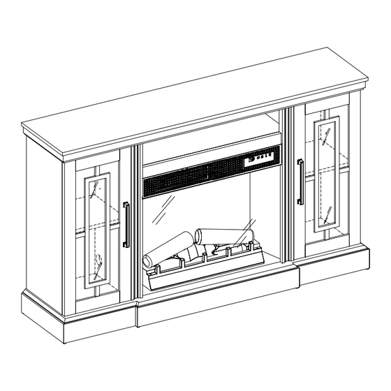
ELECTRIC FIREPLACE
MEDIA MANTEL
MODEL # 150182 / 28MMP7146-PG77
MODEL # 149155 / 28MMP7146-PB01
Español p. 27
Advertisement
Chapters
Table of Contents

Subscribe to Our Youtube Channel
Related Manuals for LF Allen + Roth 150182/28MMP7146-PG77


Summary of Contents for LF Allen + Roth 150182/28MMP7146-PG77
- Page 1 ITEM # 3730313, 4976265 ELECTRIC FIREPLACE MEDIA MANTEL ALLEN+ROTH and logo design are trademarks or registered trademarks of LF, LLC. MODEL # 150182 / 28MMP7146-PG77 All rights reserved. MODEL # 149155 / 28MMP7146-PB01 Español p. 27 Serial Number: Purchase Date: Questions, problems, missing parts? Before returning to your retailer, call our customer service department at 1-866-439-9800, 8 a.m.
-
Page 2: Table Of Contents
TABLE OF CONTENTS Product Specifications ..........................2 Safety Information.............................3 Maximum Load............................Package Contents.............................6 Hardware Contents...........................8 Preparation.............................. Assembly Instructions..........................9 Operating Instructions..........................19 Troubleshooting............................. FCC/IC Information..........................22 Care and Maintenance..........................22 Warranty..............................Battery Replacement..........................24 Replacement Parts List......................... PRODUCT SPECIFICATIONS VOLTAGE 120VAC, 60 Hz AMPS 12.5 Amps WATTS 1500 Watts 28MMP7146REV1.0... -
Page 3: Safety Information
SAFETY INFORMATION When using electrical appliances, basic precautions should always be followed to reduce the risk of fire, electrical shock, and injury to persons including the following: 1. Read all instructions before using this appliance. 2. DANGER – High temperatures may be generated under certain abnormal conditions. Do not partially or fully cover or obstruct the front of this heater. - Page 4 12. Do not insert or allow foreign objects to enter any ventilation or exhaust opening as this may cause an electric shock or fire, or damage the appliance. 13. To prevent a possible fire, do not block air intakes or exhaust in any manner. Do not use on soft surfaces, like a bed, where opening may become blocked.
-
Page 5: Maximum Load
MAXIMUM LOAD MAXIMUM LOAD 13.6 kg / 30 lb MAXIMUM LOAD 27.3 kg / 60 lb MAXIMUM LOAD 6.8 kg / 15 lb MAXIMUM LOAD 9.1 kg / 20 lb WARNING Loads heavier than the maximum weights specified may result in instability, causing tip over resulting in death or serious injury. -
Page 6: Package Contents
PACKAGE CONTENTS 28MMP7146REV1.0... - Page 7 PACKAGE CONTENTS PART DESCRIPTION QUANTITY Base Left Partition Fixed Shelf Right Partition Glass Panel Left Side Panel Top Panel Right Side Panel Back Side Panels Upper Back Panel Left Door Right Door Adjustable shelf Electric Fireplace Back Panel Front Panel with Control Button Heater Box Logset Left Logset Right...
-
Page 8: Hardware Contents
HARDWARE CONTENTS Note: USB to AC adapter is not included. USB output Ø3x12mm Ø6.3x12mm Door Bumper Wire clip 980# Screw Bolt Qty: 2 Qty: 4 Qty: 1 Qty: 2 Qty: 4 Ø3x12mm Ø3.5x12mm Ø3x15mm Ø4x12mm Ø4x50mm Screw Screw Screw Bolt Screw Qty: 8 Qty: 2... -
Page 9: Preparation
PREPARATION Before beginning assembly of product, make sure all parts are present. Compare parts with package contents list and hardware contents list. If any part is missing or damaged, do not attempt to assem- ble, install or operate the product. To protect the product from possible scratches, please assemble the parts on a scratch-free surface. - Page 10 ASSEMBLY INSTRUCTIONS 3. Attaching the Door Bumpers • Attach the Door Bumpers (EE) to the Left and Right Partitions (B and D) as shown, using Screws (FF) and a Phillips screwdriver. Hardware Used Door Bumper Ø3x15mm Screw 4. Attaching the center assembly •...
- Page 11 ASSEMBLY INSTRUCTIONS 6. Assembling the fireplace • Locate the Front Panel with Control Button (EA). • Using Screws (HH), secure the Front Panel with Control Button (EA) between the Left and Right Partitions (B and D) and just below the Top Surround Rail as shown.
- Page 12 ASSEMBLY INSTRUCTIONS 9. Placing the glass front • Turn the unit over so that Control Panel Support is now facing upward. • Locate the Glass Panel (E). • Carefully insert the Glass Panel (E) into the grooves of the surround rails as shown. Slide all the way in until the glass meets the bottom of the Control Support Panel.
- Page 13 ASSEMBLY INSTRUCTIONS 12. Attaching the back panels • Locate the Back Side Panels (I) and Upper Back Panel (J). • Slide the Back Side Panels (I) into the grooves between the inner and outer side panels as shown. Slide all the way down until the Back Side Panels (I) meet the bottom shelf.
- Page 14 ASSEMBLY INSTRUCTIONS 15. Preparing the doors • Locate the Left Door (K) and Right Door (L). • Secure Euro Hinges (KK) and (LL) to the Left Door (K) using Screws (MM) on both the upper and lower hinge as indicated. •...
- Page 15 ASSEMBLY INSTRUCTIONS 18. Inserting the adjustable shelves • Locate the two Adjustable Shelves (M). • Insert the Shelf Pins (OO) into the pre-drilled holes on the inside of each cabinet side panel at your desired height. Align all pins to the same height to ensure your shelf is level.
- Page 16 ASSEMBLY INSTRUCTIONS 21. Assembling the fireplace • Place the assembled log set into the back of the unit behind the glass panel. • Push the tabs beneath the log set into the holes on the bottom panel. 22. Securing the log set •...
- Page 17 ASSEMBLY INSTRUCTIONS 24. Securing the fireplace back panel • Align the Metal Panel Bracket (SS) behind the Fireplace back panel and above the pre-drilled hole in the Base. • Secure with the mounting Screw (TT). Hardware Used Metal Panel Bracket Ø4x15mm Screw 25.
- Page 18 ASSEMBLY INSTRUCTIONS 27. Installing the tip restraint hardware • When the Tipping Restraint Hardware (RR) is properly installed, it can provide protection against unexpected tipping of the Unit due to small tremors, bumps or climbing. • Each Tipping Restraint Hardware (RR) includes one Unit Anchor, one Wall Anchor, one Anchor Tether, and four Anchor Screws.
-
Page 19: Operating Instructions
OPERATING INSTRUCTIONS CONTROL PANEL LOCATION FUNCTION ICON DESCRIPTION There are 5 brightness levels that can be selected and OFF (00) FLAME setting. Settings F5 - F1 decrease in brightness. Press the heater button on the control panel to turn on/off (00) and HEATER adjust the heater setting. - Page 20 FUNCTION ICON DESCRIPTION This product is equipped with a Safer Plug ® ; an advanced ® SAFER PLUG safety device that helps prevent electrical fires caused from faulty outlets. Overloading of outlets, adapters and surge protectors may cause overheating, damage, and increase risk of fires. Safer Plug ®...
-
Page 21: Troubleshooting
TROUBLESHOOTING PROBLEM POSSIBLE CAUSE CORRECTIVE ACTION Unplug the fireplace, remove the back panel of the heater box and check that the thermostat is plugged The thermostat sensor is Display shows“ ” into the main circuit board. If this does not solve the broken or disconnected. -
Page 22: Fcc/Ic Information
FCC/IC INFORMATION Warning: Changes or modifications to this unit not expressly approved by the party responsible for compliance could void user’s authority to operate the equipment. NOTE: This equipment has been tested and found to comply with the limits for Class B digital device, pursuant to part 15 of the FCC Rules. -
Page 23: Warranty
1-YEAR LIMITED WARRANTY The manufacturer warrants that your new Electric Fireplace is free from manufacturing and material defects for a period of one year from date of purchase, subject to the following conditions and limitations. 1. Install and operate this appliance in accordance with the installation and operating instructions furnished with the product at all times. -
Page 24: Battery Replacement
REPLACING THE REMOTE CONTROL BATTERY: NOTE: Battery disposal Please always dispose of batteries at a suitable recycling point. CR2025 1pcs CR2025 included CAUTION: • Do not ingest battery. • Non-rechargeable battery is not to be recharged. • Battery is to be inserted with the correct polarity. •... -
Page 25: Replacement Parts List
REPLACEMENT PARTS LIST For replacement parts, call our customer service department at 1-866-439-9800, 8 a.m. - 8 p.m., EST, Monday - Sunday. You could also contact us at partsplus@lowes.com. PART PART NAME PART NUMBER Thermostat Sensor Y21-S307-P186 Blower/ Heater Assembly Y21-S307-P01 Main Circuit Board Y21-S307-P15... - Page 26 Printed in Vietnam 28MMP7146REV1.0...
- Page 27 REPSIA CON CHIMENEA ELÉCTRICA Y SISTEMA DE AUDIO Y TV ALLEN+ROTH y el diseño del logotipo son marcas comerciales o marcas registradas de LF, LLC. MODELO N.º 150182 / 28MMP7146-PG77 Todos los derechos reservados. MODELO N.º 149155 / 28MMP7146-PB01 Español p. 27 Número de serie:...
-
Page 28: Especificaciones Del Producto
ÍNDICE Especificaciones del producto.........................28 Información de seguridad........................29 Carga máxima............................Contenido del paquete..........................32 Aditamentos ............................35 Preparación............................Instrucciones de ensamblaje........................36 Instrucciones de funcionamiento......................45 Solución de problemas........................... Información sobre la FCC/IC........................49 Cuidado y mantenimiento........................49 Garantía..............................Reemplazo de la batería.........................51 Lista de piezas de repuesto........................ESPECIFICACIONES DEL PRODUCTO VOLTAJE 120 VCA, 60 Hz... -
Page 29: Información De Seguridad
INFORMACIÓN DE SEGURIDAD Cuando utilice electrodomésticos eléctricos, siempre tome medidas de precaución básicas para evitar incendios, descargas eléctricas y lesiones personales. Entre las medidas: 1. Lea todas las instrucciones antes de usar este electrodoméstico. 2. PELIGRO: se pueden generar altas temperaturas debido a ciertas condiciones que no son normales. - Page 30 12. No introduzca objetos extraños ni permita que estos entren en las aberturas de ventilación o escape, ya que podrían provocar descargas eléctricas, incendios o daños en el electrodoméstico. 13. Para evitar incendios, no bloquee las entradas ni salidas de aire de ninguna manera. No use el producto sobre superficies blandas, como una cama, donde las aberturas se puedan bloquear.
-
Page 31: Carga Máxima
CARGA MÁXIMA CARGA MÁXIMA 13,6 kg / 30 lb CARGA MÁXIMA 27,3 kg / 60 lb CARGA MÁXIMA 6,8 kg / 15 lb CARGA MÁXIMA 9,1 kg / 20 lb ADVERTENCIA Las cargas más pesadas que la capacidad máxima especificada pueden causar inestabilidad, lo que provoca vuelcos que pueden causar la muerte o lesiones graves. -
Page 32: Contenido Del Paquete
CONTENIDO DEL PAQUETE 28MMP7146REV1.0... - Page 33 CONTENIDO DEL PAQUETE PART DESCRIPTION QUANTITY Base Partición izquierda Estante fijo Partición derecha Panel de vidrio Panel lateral izquierdo Panel superior Panel lateral derecho Paneles laterales posteriores Panel posterior superior Puerta izquierda Puerta derecha Repisa ajustable Panel posterior de la chimenea eléctrica Panel delantero con botón de control Caja de calentador Juego de leños izquierdo...
- Page 34 ADITAMENTOS Nota: no se incluye el adaptador USB a CA. Tornillo de Salida USB Perno de Protector de la Sujetador de 980# Ø3 x 12 mm Ø6,3 x 12 mm puerta cables Cant.: 2 Cant.: 4 Cant.: 1 Cant.: 2 Cant.: 4 Tornillo de Tornillo de...
-
Page 35: Aditamentos
PREPARACIÓN Antes de comenzar a ensamblar el producto, asegúrese de tener todas las piezas. Compare las piezas con la lista del contenido del paquete y la lista de aditamentos. No intente ensamblar, instalar ni utilizar el producto si alguna pieza falta o está dañada. Para proteger el producto de posibles rayones, ensamble las piezas sobre una superficie que no produzca rayones. -
Page 36: Instrucciones De Ensamblaje
INSTRUCCIONES DE ENSAMBLAJE 3. Colocación de los topes de la puerta • Fije los topes de la puerta (EE) a las particiones izquierda y derecha (B y D) como se muestra, con los tornillos (FF) y un destornillador Phillips. Aditamentos utilizados Protector de la puerta Tornillo de... - Page 37 INSTRUCCIONES DE ENSAMBLAJE 6. Ensamblaje de la chimenea • Ubique el panel delantero con el botón de control (EA). • Con tornillos (HH), fije el panel delantero con el botón de control (EA) entre las particiones izquierda y derecha (B y D), y justo debajo del riel envolvente superior, como se muestra.
- Page 38 INSTRUCCIONES DE ENSAMBLAJE 9. Colocación del vidrio frontal • Dé vuelta la unidad de modo que el soporte del panel de control quede ahora hacia arriba. • Ubique el panel de vidrio (E). • Inserte con cuidado el panel de vidrio (E) en las ranuras de los rieles envolventes, como se muestra.
- Page 39 INSTRUCCIONES DE ENSAMBLAJE 12. Colocación de los paneles posteriores • Ubique los paneles laterales posteriores (I) y el panel posterior superior (J). • Slide the Back Side Panels (I) into the grooves between the inner and outer side panels as shown.
- Page 40 INSTRUCCIONES DE ENSAMBLAJE 15. Preparación de las puertas • Ubique la puerta izquierda (K) y la puerta derecha (L). • Asegure las bisagras Euro (KK) y (LL) a la puerta izquierda (K) con los tornillos (MM) tanto en la bisagra superior como en la inferior, como se indica.
- Page 41 INSTRUCCIONES DE ENSAMBLAJE 18. Inserción de los estantes ajustables • Ubique los dos estantes ajustables (M). • Inserte los soportes para estante (OO) en los orificios pretaladrados en el interior de cada panel lateral del gabinete a la altura deseada. Alinee todos los soportes a la misma altura para garantizar que el estante está...
- Page 42 INSTRUCCIONES DE ENSAMBLAJE 21. Ensamblaje de la chimenea • Coloque el juego de leños ensamblado en la parte posterior de la unidad detrás del panel de vidrio. • Inserte las lengüetas debajo del juego de leños en los orificios del panel inferior. 22.
- Page 43 INSTRUCCIONES DE ENSAMBLAJE 24. Fijación del panel posterior de la chimenea • Alinee el soporte del panel de metal (SS) detrás del panel posterior de la chimenea y por encima del orificio pretaladrado en la base. • Asegure con el tornillo de montaje (TT). Aditamentos utilizados Soporte de panel de metal...
- Page 44 INSTRUCCIONES DE ENSAMBLAJE 27. Instalación de los aditamentos de contención antivuelcos • Cuando los aditamentos de contención antivuelcos (RR) se instalan correctamente, pueden proporcionar protección contra vuelcos inesperados de la unidad debido a pequeños temblores, golpes o subidas. • Cada aditamento de contención antivuelcos (RR) incluye un ancla de la unidad, un ancla de pared, un amarre de ancla y cuatro tornillos de anclaje.
-
Page 45: Instrucciones De Funcionamiento
INSTRUCCIONES DE FUNCIONAMIENTO UBICACIÓN DEL PANEL DE CONTROL ÍCONO FUNCIÓN DESCRIPCIÓN Hay 5 niveles de brillo que se pueden seleccionar, además del LLAMA ajuste APAGADO (00). Los ajustes F5 a F1 disminuyen en brillo. Presione el botón del calentador en el panel de control para CALENTADOR encender o apagar (00) y ajustar la configuración del calentador. - Page 46 ÍCONO FUNCIÓN DESCRIPCIÓN Este producto está equipado con un Safer Plug®; un dispositivo SAFER PLUG ® de seguridad avanzado que ayuda a prevenir incendios eléctricos causados por tomacorrientes defectuosos. La sobrecarga de los tomacorrientes, adaptadores y protectores contra sobrecargas puede causar sobrecalentamiento, daños y aumentar el riesgo de incendios.
-
Page 47: Solución De Problemas
SOLUCIÓN DE PROBLEMAS PROBLEMA CAUSA POSIBLE ACCIÓN CORRECTIVA Desenchufe la chimenea, retire el panel posterior de la caja del calentador y revise que el termostato El sensor del termostato La pantalla muestra esté enchufado en la placa del circuito principal. Si está... - Page 48 PROBLEMA CAUSA POSIBLE ACCIÓN CORRECTIVA No hay baterías. Cambie las baterías del control remoto. Ponga en funcionamiento el transmisor remoto a un ritmo lento y medido. Presione los botones del control remoto con un movimiento uniforme y un Señal débil. El control remoto no nivel de presión suave.
-
Page 49: Información Sobre La Fcc/Ic
INFORMACIÓN SOBRE LA FCC/IC Advertencia: los cambios o las modificaciones a esta unidad que no estén expresamente aprobadas por la parte responsable del cumplimiento podrían anular la autorización del usuario para utilizar el equipo. NOTA: este equipo se probó y se verificó que cumple con los límites para un dispositivo digital clase B, conforme a la Sección 15 de las regulaciones de la FCC. -
Page 50: Garantía
1 AÑO DE GARANTÍA LIMITADA El fabricante garantiza que su nueva chimenea eléctrica no presentará defectos de fabricación ni en los materiales durante un período de un año a partir de la fecha de compra, siempre y cuando se cumplan las siguientes condiciones y limitaciones. 1. -
Page 51: Reemplazo De La Batería
CÓMO REEMPLAZAR LAS BATERÍAS DEL CONTROL REMOTO: NOTA: eliminación de las baterías Siempre elimine las baterías en un punto de reciclaje adecuado. CR2025 Se incluye 1 batería CR2025 PRECAUCIÓN: • No ingiera la batería. • La batería no es recargable y no debe recargarse. •... -
Page 52: Lista De Piezas De Repuesto
LISTA DE PIEZAS DE REPUESTO Para obtener piezas de repuesto, llame a nuestro Departamento de Servicio al Cliente al 1-866-439-9800, de lunes a domingo de 8 a.m. a 8 p.m., hora estándar del Este. También puede ponerse en contacto con nosotros en partsplus@lowes.com. PIEZA NOMBRE DE LA PIEZA N.º... - Page 53 Printed in Vietnam 28MMP7146REV1.0...
- Page 54 28MMP7146REV1.0...
- Page 55 28MMP7146REV1.0...
Need help?
Do you have a question about the Allen + Roth 150182/28MMP7146-PG77 and is the answer not in the manual?
Questions and answers
Allen & Roth model 3730313 I need a connection wire that attaches the heater to the control panel. It must have 10 wires instead of 8 wires. It looks like the picture but 10 prong plug in