Advertisement
Quick Links
General Features
• Standard Input Rnage
– AC Current
IA05 : AC-Amps Scaled RMS, 0-5 Amp AC
IA11 : AC-Amps True RMS, 0-5 Amp AC
– AC Voltage
IA01 : AC-Volts Scaled RMS, 200/300V AC
IA06 : AC-Volts True RMS, 200/300V AC
• Two 9 Amp Form C, and two 4 Amp Form A relays available
• Optional isolated 16 bit analog output. User or factory
scalable to 4 to 20 mA, 0 to 20 mA or 0 to 10 V across any
desired span from ± one bar to the full scale range
• Provision to connect an external programming lockout
switch.
• Optional NEMA-4 front cover.
• 24 V DC excitation is available to power external 4/20 mA
transmitters and 5 or 10 V DC excitation is available for
resistance bridge type sensors.
• Four programmable setpoints.
• Relays activation can be selected to occur above (HI) or
below (LO) each setpoint.
• UL Listed
Analog Output Scaling and Calibration . . . . . . . . . . . 9
Case Dimensions. . . . . . . . . . . . . . . . . . . . . . . . . . . 12
Component Layout . . . . . . . . . . . . . . . . . . . . . . . . . 11
Connector Pinouts . . . . . . . . . . . . . . . . . . . . . . . . . . 10
Connectors. . . . . . . . . . . . . . . . . . . . . . . . . . . . . . . . 10
Controls and Indicators . . . . . . . . . . . . . . . . . . . . . . . 2
Custom Face Plates and Scale. . . . . . . . . . . . . . . . 14
Glossary of Programming Symbols and Modes of
Operation . . . . . . . . . . . . . . . . . . . . . . . . . . . . . . . . . . 2
FL-B101Q-ACV _ FL-B01Q-ACA (d0058)
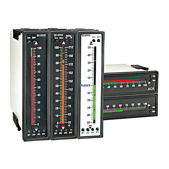
LEOPARD FAMILY
Excelent replacement for Horizontal and Vertical
Switchboard Meters, in a 9/64 Din Case (144x36mm)
Index
General Features . . . . . . . . . . . . . . . . . . . . . . . . . . . . 1
Input Module Component Glossary. . . . . . . . . . . . . . . 13
Installation . . . . . . . . . . . . . . . . . . . . . . . . . . . . . . . . 12
One Point Quickset Rescaling and Calibration
Procedure . . . . . . . . . . . . . . . . . . . . . . . . . . . . . . . . .6
Ordering Information . . . . . . . . . . . . . . . . . . . . . . . . 15
Opening the Case to Access Mode Select Headers . . .4
Overview of Display Modes, Scaling Capabilities and
Texmate, Inc. Tel. (760) 598-9899 • www.texmate.com
FL-B101Q-ACA
FL-B101Q-ACV
Leopard Bargraph Meter
AC Amps and AC Volts with RMS Option
101 Segment in a 9/64 DIN CASE
A 101 Segment Bargraph AC Volts or AC Amps
Meter Controller and Transmitter.
Specifications
Input Specs: ..............Depends on range and function selected
A/D Converter: ..........14 bit single slope
Accuracy: ..................±(0.05% of reading + 1segment)
Temp. Coeff.: .............100 ppm/°C (Typical)
Warm up time: . ..........2 minutes
Conversion Rate: . .....10 conversions per second (Typical)
Bargraph Display: . ....101
horizontal (optn), red (std), green (optn),
Positive Overrange: . .Bargraph display flashes
Negative Overrange: First segment of bargraph display flashes
Relay Output: ............Two 4 Amp Form A relays and Two
9 Amp Form C relays
Analog Output: .........Isolated 16 bit user scalable mA or V
OIC (mA out) . ..........4-20 mA @ 0 to 500Ω max loop resistance
OIV (volts out) . ......... 0-10 V DC @ 500 Ω or higher resistance
Power Supply: . ..........AC/DC Auto sensing wide range supply
PS1 (std) ................85-265 VAC, 50-400 Hz / 95-300 VDC @ 4.2W
PS2 .........................15-48 VAC,50-400 Hz / 10-72 VDC @ 4.2W
Operating Temp.: ......0 to 50°C
Storage Temp: . ..........–20°C to 70°C
Relative Humidity: ....95% (non condensing)
Case Dimensions: ....3/32 DIN, Bezel: 36x144 mm(1.42"x5.69")
Depth behind bezel: (4.64") 117.5 mm
Plus 10 mm (0.39") for Right-angled con-
nector, or plus 18.3 mm (0.72") for Straight-
thru connector, or plus 26.5 mm (1.05") for
Push-On connector.
Weight: . ......................9.5 oz., 12 oz when packed
Operation Modes . . . . . . . . . . . . . . . . . . . . . . . . . . . . 3
Pin Descriptions . . . . . . . . . . . . . . . . . . . . . . . . . . . . 10
Setpoint Adjust . . . . . . . . . . . . . . . . . . . . . . . . . . . . . . 7
Setting the Colors . . . . . . . . . . . . . . . . . . . . . . . . . . . 8
Specifications . . . . . . . . . . . . . . . . . . . . . . . . . . . . . . . 1
Standard Display Mode Calibration Procedure. . . . . 6
Two Point Quickset Scaling and Calibration . . . . . . . 5
segment
4"
vertical
Page 1
(std),
Advertisement

Subscribe to Our Youtube Channel
Related Manuals for Texmate LEOPARD FL-B101Q-ACA


Summary of Contents for Texmate LEOPARD FL-B101Q-ACA
- Page 1 Operation ........2 FL-B101Q-ACV _ FL-B01Q-ACA (d0058) Texmate, Inc. Tel. (760) 598-9899 • www.texmate.com Page 1...
- Page 2 Input Low Mode 3 Enables the Hysteresis mode for tank MODE filling or tank emptying applications. Relay Activation Mode Select Header When two fingers are shown side by side, the two corresponding buttons must be pressed at the same time to initiate an When no jumper clips are installed the relays will activate when the display exceeds the set point. indicated function. Zero Span Any relay that has a jumper clip installed will RELAYS activate when the display is less than the set point. Page 2 Texmate, Inc. Tel. (760) 598-9899 • www.texmate.com FL-B101Q-ACV _ FL-B01Q-ACA (d0058)
- Page 3 SP1 Tank Filling Tank starts emptying when level is at or • For a tank emptying application SP1 is set to a High (h) Setpoint. SP1 can control a pump that empties the above SP2 tank. With Mode 3 selected, SP1 relay activates for inputs greater than the SP2 level. Once activated, SP1 Tank stops relay will stay ON until the tank is emptied to the SP1 level. emptying when level is at SP1 Tank Emptying FL-B101Q-ACV _ FL-B01Q-ACA (d0058) Texmate, Inc. Tel. (760) 598-9899 • www.texmate.com Page 3...
- Page 4 4 to 20 mA (0 to 20 mA) 0 to 10 V DC Selection Position Selection Position Relay Activation Mode Select Header Optional 16 Bit Isolated Analog Output Module Page 4 Texmate, Inc. Tel. (760) 598-9899 • www.texmate.com FL-B101Q-ACV _ FL-B01Q-ACA (d0058)
- Page 5 6. The larger the difference between two points used for calibration, the better the accuracy. However if the difference is too high, and the output from the input signal conditioning module is greater than +2.1VDC, or less than -1.05VDC, the bar will flash over range. The calibration will not then be accepted and, the previous scaling will still be retained in memory. In this case, either a lower input signal must be used, or a higher range on the input module should be selected to recalibrate the meter. Note: Most input signal conditioners have provisions for analog calibration and scaling. If the meter’s scale factor is set to read zero with a zero input (shorted input), and to read 10 Bars fullscale with a 2.000 V input, any pre-calibrated signal conditioner with an output that does not exceed – 1 V to + 2 V, will read correctly in the meter without any further calibration. FL-B101Q-ACV _ FL-B01Q-ACA (d0058) Texmate, Inc. Tel. (760) 598-9899 • www.texmate.com Page 5...
- Page 6 STEP A RECALIBRATE THE LOW INPuT SIgNAL READINg ON THE BAR bar display 1) Apply the LO input signal (0ma in this example) to the input pins. to the required The first segment will flash, indicating an under range condition. position 2) Using the ZERO button adjust the bar up to the required position. SP1 SP2 SP3 SP4 3) The FL-B101Q has now been recalibrated to read zero to fullscale for a 0 to 20 mA input. Page 6 Texmate, Inc. Tel. (760) 598-9899 • www.texmate.com FL-B101Q-ACV _ FL-B01Q-ACA (d0058)
- Page 7 SP2 activate when input is lower than set point. SP1, SP3 and SP4 activate when input is equal to or higher than set point. SP1 and SP3 activate when input is lower than set point. SP2 and SP4 activate when input is equal to or higher than set point. SP1, SP2, SP3, and SP4 all activate when input is lower than set point. SP1 and SP2 activate when input is lower than set point. SP3 and SP4 activate when input is equal to or higher than set point. 2) ADJuST THE SETPOINT FOR EACH RELAY Zero Span The setpoint for each relay is set by the front panel buttons marked SP1, SP2, SP3 and SP4. When a front panel button is pressed and held down, the associated setpoint is directly changed. The direction of change will be either up or down, as indicated by the UP and DOWN indicator LEDs. After the indicator LED lights up there is a 0.5 second delay before any change occurs. To reverse the direction of change, release the button and then press down again. As there are no menus or sub-menus to navigate, the programming and setup is quick and easy. Setpoints are indicated on the bar display by an ON segment if the bar is below the setpoint and with an OFF segment if the bar display is above the setpoint. SP1 SP2 SP3 SP4 FL-B101Q-ACV _ FL-B01Q-ACA (d0058) Texmate, Inc. Tel. (760) 598-9899 • www.texmate.com Page 7...
- Page 8 STEP E SELECT COLOR FOR BAR ABOVE SETPOINT 4 Select required color (i.e. Red) Hold down the SP4 button. The color of the bar segments below SP4 will cycle between red, green and orange. Release the SP4 button when the bar is the required color. Now whenever the bar is above the SP4 level it will be this color. SP1 SP2 SP3 SP4 STEP F EXIT COLOR SET MODE Turn off the power to the meter for 5 seconds and then re apply the power. The bargraph will now work with the programmed colors. Page 8 Texmate, Inc. Tel. (760) 598-9899 • www.texmate.com FL-B101Q-ACV _ FL-B01Q-ACA (d0058)
- Page 9 2) Re-power the bargraph. The two buttons will now return to their original Calibration Mode function of ZERO and SPAN. 3) Calibration is now complete and the bar is scaled for a 0 to 10V input to produce an analog output of 4 to 20mA. SP1 SP2 SP3 SP4 FL-B101Q-ACV _ FL-B01Q-ACA (d0058) Texmate, Inc. Tel. (760) 598-9899 • www.texmate.com Page 9...
- Page 10 Do Not connect live wires to termi- nal blocks, and do not insert, remove or han- dle terminal blocks with live wires connected. Pin Socket Pin Socket Pin Socket Pin Socket Page 10 Texmate, Inc. Tel. (760) 598-9899 • www.texmate.com FL-B101Q-ACV _ FL-B01Q-ACA (d0058)
- Page 11 IA11: AC Amps True RMS, 5 Amp AC 301B 065F AC AMPS RMS SPAN ADJUST AC AMPS 1A/5A Secondary Secondary HEADER Fully User Scalable Fully User Scalable RANGE FL-B101Q-ACV _ FL-B01Q-ACA (d0058) Texmate, Inc. Tel. (760) 598-9899 • www.texmate.com Page 11...
- Page 12 10mm Splash Proof Lens Cover at the factory and cannot be removed Connector (0.39") 18.3mm (0.72") 117.5mm without damage to the case. P/N.(OP-N4/144X36 ) Straight-thru (0.20") (4.64") Connector Page 12 Texmate, Inc. Tel. (760) 598-9899 • www.texmate.com FL-B101Q-ACV _ FL-B01Q-ACA (d0058)
- Page 13 200V Left Rear ed with either a single or multiple jumper clip. When meter). Typically it enables the input signal to be ZERO provided, a custom range position is only functional offset ±5% of full scale (-100 to +100 counts). Turn Clockwise to Increase Reading when the option has been factory installed. – ⊕ – ⊕ + 100 Counts 100 Counts 15 Turn Potentiometer FL-B101Q-ACV _ FL-B01Q-ACA (d0058) Texmate, Inc. Tel. (760) 598-9899 • www.texmate.com Page 13...
- Page 14 Custom Face Plates and Scales Texmate Produces Thousands of Custom OEM Face Part Number Description List Plates Small Run Custom Face plates for Bargraphs ART-NRC-DES ..Small run NRC custom faceplate design... . $100 Have Texmate Design and Build a Custom Face Plate to Suit ART-NRC-LOGO.
- Page 15 WHETHER OF MERCHANTABILITY, FITNESS FOR PURPOSE, OR OTHERWISE is made the products which shall, within the applicable period after shipment, be returned to Texmate’s beyond the repair, replacement, or refund of purchase price at the sole discretion of Texmate. facility, transportation charges pre-paid, and which are, after examination, disclosed to the sat- Users shall determine the suitability of the product for the intended application before using, and isfaction of Texmate to be thus defective. The warranty shall not apply to any equipment which the users assume all risk and liability whatsoever in connection therewith, regardless of any of shall have been repaired or altered, except by Texmate, or which shall have been subjected our suggestions or statements as to application or construction. In no event shall Texmate’s to misuse, negligence, or accident. In no case shall Texmate’s liability exceed the original pur- liability, in law or otherwise, be in excess of the purchase price of the product. chase price. The aforementioned provisions do not extend the original warranty period of any product which has been either repaired or replaced by Texmate. Texmate cannot assume responsibility for any circuitry described. No circuit patent or software licenses are implied. Texmate reserves the right to change circuitry, operating software, specifi- cations, and prices without notice at any time. FL-B01Q-ACA and FL-B101Q-ACV Technical Manual Copyright © 2018 Texmate Inc.
Need help?
Do you have a question about the LEOPARD FL-B101Q-ACA and is the answer not in the manual?
Questions and answers