Advertisement
Quick Links
Advertisement

Related Manuals for Golden Designs GDI-3356-01


Summary of Contents for Golden Designs GDI-3356-01
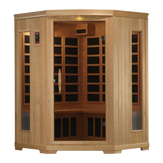
- Page 1 GDI3356 3 Person Corner Sauna OWNER’S MANUAL CARBON MODEL SAUNA FOR INDOOR USE ONLY 120VAC 20AMP Dedicated Circuit Required Carefully and thoroughly read this Owner’s Manual before using/operating the sauna. We recommend keeping this Owner’s Manual for regular review and future reference...
-
Page 2: Table Of Contents
TABLE OF CONTENTS Packing List Visual Assembly Diagrams Parts Description Assembly Instructions Operating the Sauna Tips for Using Your Sauna Safety Instructions Safeguards for Your Sauna Troubleshooting Guide Warranty Warranty Card WARNING: Visually inspect all heaters before assembly to make sure they are not damaged. -
Page 3: Are Infrared Rays Safe
What Are Infrared Rays? Infrared is the band of light we perceive as heat. We cannot see this band of light with the naked eye, but we can feel this type of light in the form of heat. Our sun produces most of its energy output in the infrared segment of the spectrum. - Page 4 an electric field and a magnetic field. The electric field is produced by stationary charges and the magnetic field by moving charges referred to as currents. Although all of our sauna products have been developed to have low EMF, this specific model uses our advance carbon panel technology which significantly reduces the amount of EMF exposure resulting in less than 10 milligauss (mG).
-
Page 5: How It Works
the world. These benefits are presented for reference purposes only and no implication of infrared saunas creating a cure for or treating any disease is implied nor should it be inferred. If you have a medical/health condition, are taking prescription drugs, or have acute joint injuries, please consult with your medical physician before using the sauna. - Page 6 discharge waste products shedding any old skin cells leaving the skin glowing and clean, with improved tone, elasticity, texture, and color. Health Benefits Include, But Are Not Limited To: *Pain relief from Rheumatoid Arthritis *Relaxes muscle spasms *Reduces cellulite *Increases blood circulation *Clears, rashes, acne *Enhances skin tone *Cardiovascular conditioning...
-
Page 7: Visual Assembly Diagrams
*PLEASE READ INSTRUCTIONS BEFORE ASSEMBLY* GDI-3356-01 *The above assembly diagram i s for a quick reference visual guide only. All sauna models are not shown. Parts and accessories may vary and are subject to change. Backrests are sold separately. -
Page 8: Parts Description
PARTS DESCRIPTION GDI-3356-01 NOTE: The pictures and diagrams shown within this owner’s manual are representations of this model. Actual model may vary. Design and Construction are subject to change. Backrests are sold separately. - Page 9 Highlights Power Supply (Control Box) The POWER SUPPLY is the control center of the sauna room. It is installed on the topside of the ROOF PANEL and has inputs/outputs connected to it. (see Figure 1) Figure 1 POWER IN - main power of the sauna room HT1, HT2, HT3, HT4, HT5, HT6 –...
- Page 10 III. CD/Radio (radio model subject to change) The multifunction stereo enhances the sauna with its FM receiver and Bluetooth capability. Figure 2 MP3 Auxiliary Port The MP3 Auxiliary Port allows you to connect a MP3 player or other device with the auxiliary function to the speakers in the sauna room for your listening pleasure.
- Page 11 Guide and Guide Inserts The guide and guide inserts are used to connect the FRONT PANEL to the LEFT SIDE PANEL and the RIGHT SIDE PANEL. (see Figure Figure 4 Panel Descriptions For easier assembly, please understand and distinguish the differences between each panel.
-
Page 12: Assembly Instructions
Heat emitter panels are closer to the top Figure 6 Assembly Instructions A. Choose a good location to assemble the sauna 1. The location must be dry, leveled, and away from any source of water 2. MAIN POWER cord must be easily accessible 3. - Page 13 Figure 7 (Floor Heater is towards the front) C. Installing the REAR PANELS 1. Remove the protection paper from the buckles. Attach the LEFT SIDE REAR PANEL to the RIGHT SIDE REAR PANEL while the panels are sitting on the FLOOR PANEL. (see Figure 8) Figure 8 D.
- Page 14 Figure 9 Figure 10 E. Installing the BENCH EMITTER PANEL, BENCH PANEL and BENCHES 1. Locate the (2) square wood frames that have two cutouts on one side and a vertical slot on the other side. Place one of the wood frames next to the glass window with the two cutouts facing the glass window and the vertical slot facing towards the front.
- Page 15 Figure 11 Figure 12 Figure 13 PLEASE NOTE: HEATER STYLES MAY VARY. G. Installing the FRONT PANEL 1. Place the FRONT PANEL onto the recessed area on the FLOOR PANEL. Align guides on the LEFT SIDE PANEL with the guide inserts on the FRONT PANEL. The LEFT SIDE PANEL will need to be lifted in order to lock the guide inserts on the LEFT SIDE PANEL into the guides on the FRONT PANEL.
- Page 16 H. Installing the ROOF PANEL 1. The side with the power supply box faces upward. 2. The edge nearest the power supply is the front of the ROOF PANEL. Be careful of the wires coming from the SIDE and REAR PANELS when you set the ROOF PANEL down onto the panels.
- Page 17 Figure 17 Figure 18 Figure 19 Figure 20 J. Installing RADIO HOUSING BOX and RADIO (radio model subject to change) 1. 1. If your RADIO HOUSING BOX is already assembled, then proceed to step D. Locate the wood sides for the RADIO HOUSING BOX. There is one for the front, side, and bottom.
- Page 18 the RADIO once you slide it into the RADIO HOUSING BOX because the RADIO will just sit in place. (see Figure 26) Figure 21 Figure 22 Figure 23 Figure 24 Figure 25 Figure 26 L. Installing the TEMPERATURE SENSOR 1. Enter the sauna and remove the protective covering from the TEMPERATURE SENSOR.
- Page 19 Figure 27 Note: Some sauna models are shipped with a spare TEMPERATURE SENSOR in case the TEMPERATURE SENSOR is damaged during transit. The manufacturer decides this according to sauna models and packaging. M. Putting on the ROOF COVER 1. Place the ROOF COVER over the top of the sauna. Be cautious when pulling the power cord through the hole in the roof cover.
-
Page 20: Installation Completed
shelf, or towel rack, use the provided screws and mount according to designated labeled locations. The optional backrest can lean directly up against the heat emitter panels. Please note that all accessories may not be for all sauna models. (see Figure 30 – Figure 34) Figure 30 (MP3 Shelf Figure 31 (Magazine Rack) Figure 32 (Cup Holder Shelf) -
Page 21: Operating The Sauna
Operating the Sauna NOTE: Before the sauna is turned on, remove plastic protective covering from the CONTROL PANELS. Please check and confirm that the connections to the POWER SUPPLY (including the power cord), HEAT EMITTERS, CD/RADIO, and TEMPERATURE SENSOR are connected properly and are snug and tight. The power supply voltage and frequency must match the requested voltage and frequency of the sauna (120VAC 20AMP Dedicated Circuit). - Page 22 1. Plug the sauna into the wall outlet. 2. Press the POWER button once. The POWER light will come on, the TIME DISPLAY will show 90 (minutes), the TEMPERATURE DISPLAY will show F / 66 C, and the control panel will flash. 3.
- Page 23 7. Reading lamps and/or roof lamps and/or color therapy lamps are operated by pressing the respective buttons located towards the center of the control panel. These lamps are offered on some models and are not available on all models. 8. Color Lighting can be operated as follows: First, you will need to install the battery.
-
Page 24: Tips For Using Your Sauna
sauna room before it has reached the set temperature. Also, the most commonly used temperature setting is between 118 degrees Fahrenheit / 48 degrees Celsius and 122 degrees Fahrenheit / 50 degrees Celsius. The way the sauna room works is when you set the Control Panel to say 120 degrees F / 49 degrees C, the heat emitters will turn off when that set temperature is reached. -
Page 25: Safety Instructions
9. To utilize the sauna’s heat therapy effect, put oil and treatment into your hair and wrap it with a towel. After your sauna session is over, rinse your hair thoroughly. 10. The peaceful and relaxed state rendered by a sauna session may help you to sleep easier and deeper. - Page 26 sauna. Some medications may induce drowsiness while other may affect the heart rate, blood pressure, and/or blood circulation. 10. Use care when exercising before and after sauna use. 11. Never sleep inside the sauna 12. Do not use any type of cleaning agents on the interior of the sauna. Only wipe down the sauna room with water and a damp cloth.
-
Page 27: Safeguards For Your Sauna
operation. If for any reason your sauna does not seem to be operating properly, discontinue use and contact Customer Service. Safeguards For Your Sauna 1. Do not install the sauna near water, near a bathtub (if water will splash on the sauna), near a shower (if water will splash on the sauna), in a wet basement, or near a swimming pool (if water will splash on the sauna). - Page 28 properly connected snug and tight to the cords on the roof and that those cords are properly plugged into the power supply (snug and tight). Solution: If some of the heat emitters are working, then the ones which are not working may have been damaged or are not properly connected. Check that the heat emitter cords are properly connected snug and tight.
- Page 29 power supply is malfunctioning or power cords are damaged, then unplug the sauna immediately and contact the Customer Service. Solution: The control panel will not turn off, the power/work/or heat lights do not come on, or the temperature and timer buttons do not work means the control panel may have been damaged and will need to be replaced.
- Page 30 2. Disconnect the "PANEL CONTROL" harnesses (both ends) and then reconnect making sure that the connection is snug and tight. 3. Also and while up on the roof, please located the temperature sensor wire. The temperature sensor is the black probe that is sticking out of the interior ceiling above your head as you sit on the bench.
- Page 31 Loose connections can also cause sparking in the junction box that can result in arcing. You'll likely see burn marks around the terminals if this happens. You will need to consult with an electrician to replace the wall outlet. You will need to contact Customer Service if the power supply cord is damaged as the power supply will need to be replaced.
- Page 32 to the breaker in your electric panel box. You have a quasi-dedicated line if you have multiple receptacles on a line to the breaker in your electric panel box and you do not draw any power from the other receptacles when the sauna is in operation.
- Page 33 Please try the following in assembling the sauna. With one person inside the sauna room and pushing on the rear wall panel outward, a second person should be able to latch the buckles. Make sure that the wall is fitting together like a puzzle as one wall panel fits into the other.
-
Page 34: Limited Lifetime Warranty
Limited Lifetime Warranty 5 Year Limited Warranty: Golden Designs, Inc. under the Dynamic brand name warranties the wood, structure, heating elements, and electronics against defects in material and workmanship for a period of 1 to 5 years from the original date of purchase. This sauna is for INDOOR use only. - Page 35 Use of lacquer or paints Sauna and other Golden Designs, Inc. products accessories placed on non- approved surfaces Outdoor applications Normal wear and tear or weathering Use of product not in accordance with instructions Worn out receptacle Surface cracks are not considered defects in material or workmanship, as they are normal characteristics of all woods.
- Page 36 PAGE INTENTIONALLY LEFT BLANK...
-
Page 37: Warranty Card
WARRANTY CARD Congratulations on your purchase of an Infrared Sauna from Golden Designs, Inc. Please take the time to complete the following Warranty Card and mail it back to: Golden Designs, Inc. 3550 Jurupa Street, Unit B Ontario, CA 91761 Please include a copy of your sales receipt showing date of purchase as this will serve as proof of purchase.
Need help?
Do you have a question about the GDI-3356-01 and is the answer not in the manual?
Questions and answers