
Subscribe to Our Youtube Channel
Related Manuals for dacell DN-1000A


Summary of Contents for dacell DN-1000A
- Page 1 Ver 1.0 MODEL : DN-1000A Digital indicator (AC Type) User's Manual DACELL CO.,LTD. Address : 681-1 Cheoksan -Ri ,Nami - Myeon , Cheongwon - Gun ,Chung-Buk,Korea TEL : 043-260-2242 FAX : 043-260-2245 http://www.dacell.com E-Mail : dana@danaloadcell.com...
- Page 2 Contents 1. Sepcial Features ⋅⋅⋅⋅⋅⋅⋅⋅⋅⋅⋅⋅⋅⋅⋅⋅⋅⋅⋅⋅⋅⋅⋅⋅⋅⋅⋅⋅⋅⋅⋅⋅⋅⋅⋅⋅⋅⋅⋅⋅⋅⋅⋅⋅⋅⋅⋅⋅⋅⋅⋅⋅⋅⋅⋅⋅⋅⋅⋅⋅⋅⋅⋅⋅⋅⋅⋅⋅⋅⋅⋅⋅⋅⋅⋅⋅⋅⋅⋅⋅⋅⋅⋅⋅⋅⋅⋅⋅⋅⋅⋅⋅⋅⋅⋅⋅⋅⋅⋅⋅⋅⋅⋅⋅⋅⋅⋅⋅⋅⋅⋅⋅⋅⋅⋅⋅⋅ 2 1-1. High-speed conversion method ⋅⋅⋅⋅⋅⋅⋅⋅⋅⋅⋅⋅⋅⋅⋅⋅⋅⋅⋅⋅⋅⋅⋅⋅⋅⋅⋅⋅⋅⋅⋅⋅⋅⋅⋅⋅⋅⋅⋅⋅⋅⋅⋅⋅⋅⋅⋅⋅⋅⋅⋅⋅⋅⋅⋅⋅⋅⋅⋅⋅⋅⋅⋅⋅⋅⋅⋅⋅⋅⋅⋅⋅⋅⋅⋅⋅⋅⋅⋅ 2 1-2. Calibration method ⋅⋅⋅⋅⋅⋅⋅⋅⋅⋅⋅⋅⋅⋅⋅⋅⋅⋅⋅⋅⋅⋅⋅⋅⋅⋅⋅⋅⋅⋅⋅⋅⋅⋅⋅⋅⋅⋅⋅⋅⋅⋅⋅⋅⋅⋅⋅⋅⋅⋅⋅⋅⋅⋅⋅⋅⋅⋅⋅⋅⋅⋅⋅⋅⋅⋅⋅⋅⋅⋅⋅⋅⋅⋅⋅⋅⋅⋅⋅⋅⋅⋅⋅⋅ 2 1-3. HOLD & PEAK HOLD ⋅⋅⋅⋅⋅⋅⋅⋅⋅⋅⋅⋅⋅⋅⋅⋅⋅⋅⋅⋅⋅⋅⋅⋅⋅⋅⋅⋅⋅⋅⋅⋅⋅⋅⋅⋅⋅⋅⋅⋅⋅⋅⋅⋅⋅⋅⋅⋅⋅⋅⋅⋅⋅⋅⋅⋅⋅⋅⋅⋅⋅⋅⋅⋅⋅⋅⋅⋅⋅⋅⋅⋅⋅⋅⋅⋅⋅⋅⋅⋅⋅⋅⋅⋅⋅⋅ 2 1-4. Comparison Output ⋅⋅⋅⋅⋅⋅⋅⋅⋅⋅⋅⋅⋅⋅⋅⋅⋅⋅⋅⋅⋅⋅⋅⋅⋅⋅⋅⋅⋅⋅⋅⋅⋅⋅⋅⋅⋅⋅⋅⋅⋅⋅⋅⋅⋅⋅⋅⋅⋅⋅⋅⋅⋅⋅⋅⋅⋅⋅⋅⋅⋅⋅⋅⋅⋅⋅⋅⋅⋅⋅⋅⋅⋅⋅⋅⋅⋅⋅⋅⋅⋅⋅⋅⋅⋅⋅⋅ 2 1-5. Data Back-up ⋅⋅⋅⋅⋅⋅⋅⋅⋅⋅⋅⋅⋅⋅⋅⋅⋅⋅⋅⋅⋅⋅⋅⋅⋅⋅⋅⋅⋅⋅⋅⋅⋅⋅⋅⋅⋅⋅⋅⋅⋅⋅⋅⋅⋅⋅⋅⋅⋅⋅⋅⋅⋅⋅⋅⋅⋅⋅⋅⋅⋅⋅⋅⋅⋅⋅⋅⋅⋅⋅⋅⋅⋅⋅⋅⋅⋅⋅⋅⋅⋅⋅⋅⋅⋅⋅⋅⋅⋅⋅⋅ 2 1-6. Watch dog ⋅⋅⋅⋅⋅⋅⋅⋅⋅⋅⋅⋅⋅⋅⋅⋅⋅⋅⋅⋅⋅⋅⋅⋅⋅⋅⋅⋅⋅⋅⋅⋅⋅⋅⋅⋅⋅⋅⋅⋅⋅⋅⋅⋅⋅⋅⋅⋅⋅⋅⋅⋅⋅⋅⋅⋅⋅⋅⋅⋅⋅⋅⋅⋅⋅⋅⋅⋅⋅⋅⋅⋅⋅⋅⋅⋅⋅⋅⋅⋅⋅⋅⋅⋅⋅⋅⋅⋅⋅⋅⋅⋅⋅⋅⋅⋅⋅⋅⋅⋅⋅⋅⋅⋅⋅⋅⋅⋅⋅⋅⋅⋅⋅⋅⋅⋅⋅ 2 1-7. Option ⋅⋅⋅⋅⋅⋅⋅⋅⋅⋅⋅⋅⋅⋅⋅⋅⋅⋅⋅⋅⋅⋅⋅⋅⋅⋅⋅⋅⋅⋅⋅⋅⋅⋅⋅⋅⋅⋅⋅⋅⋅⋅⋅⋅⋅⋅⋅⋅⋅⋅⋅⋅⋅⋅⋅⋅⋅⋅⋅⋅⋅⋅⋅⋅⋅⋅⋅⋅⋅⋅⋅⋅⋅⋅⋅⋅⋅⋅⋅⋅⋅⋅⋅⋅⋅⋅⋅⋅⋅⋅⋅⋅⋅⋅⋅⋅⋅ 3 1-8.
- Page 3 Special Features We thank you for using our product. Please refer to this manual or contact our office if you find any problems during using our product. This product, an indicator displaying micro-voltage signal in digital amplified from differential trans sensors, is used for fast-measurement of LVDT, brushlesstype torquemeter.
- Page 4 1-7. Option You can use BCD, RS232C, RS485 and 4 relay output as the optional specification. 1-8. Power AC 85 ~ 265V 50/60Hz Free voltage...
- Page 5 2. Attention For the efficient and safe use, please carefully read and be fully aware of the following details before using this product. It is strictly forbidden to use this product for any other purpose of use or to attempt to make any alteration on this product.
- Page 6 3. Specification • Available sensor : differential trans sensors - LVDT, brushlesstype torquemeter TORQUE • Upper limit Display : -19999 ~ +99999 • A/D Converter : 24bit, 1000 times/sec • D/A Converter : 16bit • Temperature Characteristic (Amp Characteristic) Zero : 0.5μV/℃...
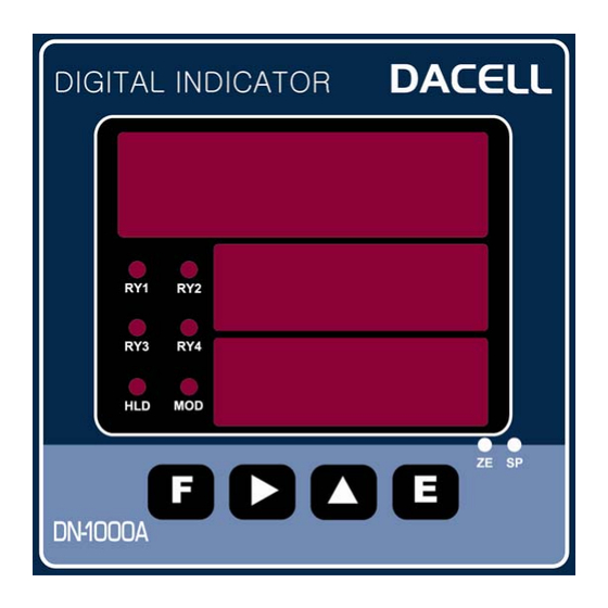
- Page 7 4. Front Panel ① Measure value : Indicate measured value or setting value. ②,③ Setting value HI, LO : Indicate setting value HI, LO ④ Relay LED : Light a LED when measured data are beyond setting value or less. ⑤...
- Page 8 5. Rear Panel Please check the location of terminal and its use. While the projected button is being pressed, please insert the cable into the lower hole completely. As soon as you release the button, the connection will be completed. At the point, please slightly pull the calbe and check whether the cable is come off or not.
- Page 9 ⑩ GND : External Input Common Terminal ⑪ IN1 : External HOLD Input Terminal ⑫ IN2 : External ZERO Input Terminal ⑬ IN3 : External printer signal Input Terminal (when PT-100 use) ⑭ IN4 : No use ⑮ COM : RELAY Output Common Terminal ○...
- Page 10 6.Wiring Diagram <Wiring Diagram> <Example - External Input PLC Connection>...
- Page 11 7. Components & Function 7-1. Flow Chart sensor input A/D conversion 1000 times/s RPM Pulse count Fixed filter Average : 32 times Output count : 32 times/s Display filter Display update rate : 1~32times/s Average : 1 ~ 32times/s Display peak hold Display D/A conversion Analog output 1 ~32 times/s...
- Page 12 7-2. How to use Hold mode Hold mode is largely divided into Peak Hold and Sample Hold. Please select Analog, Digital or Display Hold as per your purpose of use (Hi or Low Speed) To input Hold, you can use Hold key on the front panel or external input. For the operation method, please refer to the drawing below.
- Page 13 7-3. How to use comparison ouput function For comparison output function, there are 3 different modes such as Decision, High limit, Low limit. It displays through the relay of rear panel comparing each setup value. On High limit and Low limit mode, Hysteresis can be used. To set up upper limit (High) and lower limit(Low), please use the key on the front panel.
- Page 15 8. Setting Modes 8-1. Types of Setting mode & Set-up For Setting mode, there are 4 different types of mode such as Function mode, Digital calibration mode, Actual load calibration mode and SPAN constant calibration mode. Measuring Mode While being key.
- Page 16 8-2. Function mode 1) How to set up function Measuring Mode State key is being While pressed, press key.
- Page 17 1) How to set RELAY data ① Decision mode (Decision mode : mode 0) Prees Lo,Hi key on front panel and input data. ② Limit mode ( : mode 1 ~ 3) Low & High limit mode Measuring Mode press Input data...
- Page 18 # Function mode list # Name Function Setting 출고시 기준설정값 F-01 Decimal point 0, 1, 2, 3 F-02 Division 1, 2, 5, 10, 20, 50 F-03 Display filter 0, 4, 8, 16, 32 F-04 Hold mode Display SH, Display PH(+), Absolute PH(±) Display PH(+) Comparison mode Display SH, Digital SH, Display PH(+),...
- Page 19 F-02. Division (Minimum display unit setup) (Standard setup value : 1) Display data Setting Displayed In 1 (0, 1, 2, 3, 4 …….) Displayed in 2 (0, 2, 4, 6, 8 …….) Displayed in 5 (0, 5, 10, 15 …….) Displayed in 10 (0, 10, 20, 30 …….) Displayed in 20...
- Page 20 : Relay RY1, RY2, RY3, RY4 출력 Low & High limit mode F-06. Hysteresis (Standard setup value : 00) Display data Setting : Hysteresis – not used 01 ~99 : Hysteresis – used (Decision mode is not applied) F-07. DAC mode (Analog Output mode setup) (Standard setup value : 0) Display data Setting...
- Page 21 by command) F-10. Baud rate (Communication Speed Setup) (Standard setup value : 9.60) Display data Setting Stream mode Command mode 2.40 2400 bps 4.80 4800 bps 9.60 9600 bps 19.20 19200 bps 38.40 38400 bps 57.60 57600 bps PRINT PRINT DATA OUT (PT-100) F-11.
- Page 22 F-14. Key disabling (Front key Locking setup) (Standard setup value : 0000) Display data Setting Hold key Lock (1), Release (0) Hi key Lock (1), Release (0) Lo key Lock (1), Release (0) Zero key Lock (1), Release (0) <Set-up example> 1001 : Zero &...
- Page 23 8-3. Digital calibration (Calibration by sensor output value) At the time of purchasing sensor, the rated capacity (R.C) and rated output (R.O) declared on the calibration sheet can be used for the calibration for easier calibration. Measuring Mode State key is being While pressed, press key.
- Page 24 8-4. Actual load calibration This is a calibration method by adding actual load on the sensor. Standard weight is Needed. Measuring Mode State key is being pressed, press key. While Displays Function Mode State Displays Sensor Ouput Value Calibration State Displays Actual Load Calibration State Displays the Rated output value input state Input the rated output value by using...
- Page 25 8-5. SPAN constant claibration Calibratuib by Shunt CAL Value You can calibrate without any standard weight. It is to calibrate with the S.CAL value written down for load calibration. Measuring Mode State key is being While pressed, press key. Displays Function Mode State Displays Sensor Ouput Value Calibration State Displays Actual Load Calibration State Displays Shunt cal value Calibration state...
- Page 26 8-6. DATA BACK-UP & RESTORE You can save all the set-up values of the device and then restore them to the current set-up state as per your need. ◦ DATA BACK-UP : Save the current set-up state. ◦ RESTORE : Restore the current set-up state. 1) DATA BACK-UP Measuring Mode State key is being...
- Page 27 8-7. Lock Set-up You can prevent any accidental operation due to the unnecessary key control by Lock set-up. After finishing calibration, it is recommended to set the Lock. At the first stage, please start while the power is OFF. Related Function when Lock is set : Function related to calibration, DATA BACK-UP &...
- Page 28 9. Product Inspection Symptom Cause Action Remark • Insulation • • Load cell input, output. Load cell is damaged. • Check resistance • Load cell insulation When Display resistance • Check load cell’s trembles. (Cable & Case > resistance. • Indirect occurrence insulation resistance.
- Page 29 10. OPTION # Option 01(BCD OUT INTERFACE) This Parallel BCD interface is the output for the weight value made into BCD coding. available for PLC(Parallel Logic Control), Computer. This interface is • PIN ASSIGNMENT PIN No. SIGNAL PIN No. SIGNAL 4 ×...
- Page 30 • Signal output DATA output TIME(T) can set to Function BCD Mode. (10, 20, 50, 100, 200, 500, 1000㎳) Note) Please set to DISPLAY BUFFER's set point low if you want to high speed DATA Output. (BUFFER 1 ≒ 0.2ms) •...
- Page 31 #Option-02 (RS232C) Since RS232C Interface is very sensitive of electric noise. So please do the wiring from AC Power and electric wires separately. Also you must use the shield calbe always. Indicator Host PC TX(Transmission Data) RXD(Receive Datea), No.2 Pin RX(Receive Datea) TXD(Transmission Data), No.3 Pin GN(Ground)
- Page 32 4) BYTE15 : CARRIAGE RETURN 5) BYTE16 : LINE FEED 7. Command mode : Please setup as RS485 mode and use.( Refer to OP- 03:RS485 )
- Page 33 #Option-03 (RS485) Since RS485 Interface is very sensitive of electric noise. So please do the wiring from AC Power and electric wires separately. Also you must use the shield calbe always. 1. TYPE : RS485 2. Method : Half-duplex, asynchronous method 3.
- Page 34 9. Transmission Data Form (INDICATOR -> PC) CODE BYTE1 BYTE2 BYTE3 BYTE4 BYTE5 BYTE6 BYTE7 BYTE8 ASCII CODE BYTE9 BYTE10 BYTE11 BYTE12 BYTE13 BYTE14 BYTE15 BYTE16 ASCII 1) BYTE1, BYTE2 : Fixed Charactor (ID) 2) BYTE3 ~ BYTE5 : Device number (1 ~ 32) 3) BYTE6 : Fixed Charactor (,) 4) BYTE7~BYTE14 : DATA 8byte (Including +/- )
Need help?
Do you have a question about the DN-1000A and is the answer not in the manual?
Questions and answers