Table of Contents
Advertisement
Quick Links
Advertisement
Table of Contents

Related Manuals for dacell DN-130T


Summary of Contents for dacell DN-130T
- Page 1 DIGITAL INDICATOR USER’S MANUAL DN-130T (VER 4.0) DN-130L (VER 4.0) DN-230A (VER 1.0) DACELL CO.,LTD. Address : 681-1 Cheoksan-Ri, Nami-Myeon, Cheongweon-Gun, Chung-buk TEL :82-43-260-2242 FAX : 82-43-260-2245 http://www.dacell.com E-Mail : info@dacell.com...
-
Page 2: Table Of Contents
8-3. Digital calibration (Calibration by sensor output value) ⋅⋅⋅⋅⋅⋅⋅⋅⋅⋅⋅⋅⋅⋅⋅⋅⋅⋅⋅⋅⋅⋅⋅⋅⋅⋅⋅⋅⋅⋅⋅⋅⋅⋅⋅⋅⋅⋅⋅⋅⋅⋅⋅ 20 1) DN-130T, DN-230A ⋅⋅⋅⋅⋅⋅⋅⋅⋅⋅⋅⋅⋅⋅⋅⋅⋅⋅⋅⋅⋅⋅⋅⋅⋅⋅⋅⋅⋅⋅⋅⋅⋅⋅⋅⋅⋅⋅⋅⋅⋅⋅⋅⋅⋅⋅⋅⋅⋅⋅⋅⋅⋅⋅⋅⋅⋅⋅⋅⋅⋅⋅⋅⋅⋅⋅⋅⋅⋅⋅⋅⋅⋅⋅⋅⋅⋅⋅⋅⋅⋅⋅⋅⋅⋅⋅⋅⋅⋅⋅⋅⋅ 20 2) DN - 130L ⋅ ⋅⋅⋅⋅ ⋅ ⋅⋅⋅ ⋅⋅⋅ ⋅ ⋅⋅⋅⋅ ⋅⋅ ⋅⋅ ⋅⋅⋅ ⋅⋅⋅ ⋅ ⋅⋅ ⋅⋅ ⋅⋅ ⋅⋅ ⋅⋅⋅⋅ ⋅⋅ ⋅⋅ ⋅⋅ ⋅⋅ ⋅⋅ ⋅⋅ ⋅⋅ ⋅⋅ ⋅⋅ ⋅ ⋅⋅ ⋅⋅ ⋅ ⋅⋅⋅⋅⋅ ⋅⋅ ⋅⋅⋅ ⋅⋅ ⋅⋅ ⋅⋅ ⋅⋅ ⋅⋅ ⋅⋅ ⋅ ⋅⋅ 21 8-4. -
Page 3: Sepcial Features
Special Features We are grateful to you for picking up our product. If you experience problems while using it, you may refer to the user manual or contact the Technical Support Department of the company. This product is an indicator which displays Torque and RPM in digital mode and it has the following features. -
Page 4: Attention
2. Attention For the efficient and safe use, please carefully read and be fully aware of the following details before using this product. It is strictly forbidden to use this product for any other purpose of use or to attempt to make any alteration on this product. -
Page 5: Specification
3. Specification DN-130T DN-130L DN-230A SPEC. Model CH1 : 0.5~3mV/V CH1,CH2 : CH1 : 0~2Vrms SIGNAL CH2 : PULSE 0.5~3mV/V CH2 : PULSE DC 0 ~ 10V, 4 ~ 20mA(in accordance with customer request) ANALOG OUT CH1 : 5V CH1 : 2Vrms/5kHz... -
Page 6: Front Panel
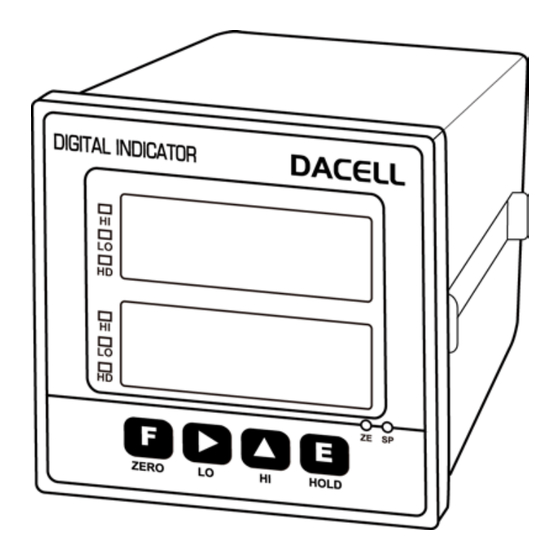
4. Front Panel ① HI, LO Indication LED : Hi or LO LED will be lighted when measured value exceeds the setting value. ② HOLD indication LED : This LED will be lighted when the measured value is on Hold. ③... -
Page 7: Rear Panel
5. Rear Panel Please check the location of terminal and its use. While the projected button is being pressed, please insert the cable into the lower hole completely. As soon as you release the button, the connection will be completed. At the point, please slightly pull the calbe and check whether the cable is come off or not. - Page 8 ⑫ GND : SHIELD connection terminal of sensor(Tare) ⑬ OUT1, 2 : Analog (DC 0 ~10V/DC 4 ~ 20mA) Output Terminal ⑭ TXD, RXD : RS232C SERIAL INTERFACE (RS485 : TXD → TX+, RXD → TX-)GND : External Input Common Terminal ⑮...
- Page 9 At the point, please slightly pull the calbe and check whether the cable is come off or not. (The most suitable calbe is Φ 0.5~1. Linking cable must be brazing or used with 1 terminal) 1) DN-130T 2) DN-130L...
- Page 10 3) DN-230A 1) <Example - External Input PLC Connection>...
-
Page 11: Components & Function
7. Components & Function 7-1. How to use Hold mode Hold mode is largely divided into Peak Hold and Sample Hold. Please select Analog, Digital or Display Hold as per your purpose of use (Hi or Low Speed) To input Hold, you can use Hold key on the front panel or external input. For the operation method, please refer to the drawing below. -
Page 12: How To Use Comparison Output Function
7-2. How to use comparison ouput function For comparison output function, there are 3 different modes such as Decision, High limit, Low limit. It displays through the relay of rear panel comparing each setup value. On High limit and Low limit mode, Hysteresis can be used. To set up upper limit (High) and lower limit(Low), please use the key on the front panel. -
Page 13: Setting Mode
8. Setting Modes 8-1. Types of Setting mode & Set-up For setting mode, there are 4 different types of mode such as Function mode, Digital calibration mode, Actual load calibration mode and SPAN constant calibration mode. Mesuring mode While key is being Press, press Function mode ①... -
Page 14: How To Set Up Function
8-2. Function mode DN-130T, DN-230A : CH1 (TORQUE), CH2 (RPM) DN-130L : CH1 (LOAD CELL), CH2 (LOAD CELL) 1)How to set function. Measuring mode While key is being, Press, press... - Page 15 3) How to set RELAY data : Lower limit setup key : Upper limit setup key Measuring mode Press key or press Input value...
- Page 16 F-01. Decimal point (Decimal point set up) (Standard setup value: 1) Display data Setting Remark 00000 : No decimal point DN-130T,DN-230A 0000.0 : One decimal place : Only set up CH1 . 000.00 : Two decimal places DN-130D : Set up CH1 and CH2 00.000...
- Page 17 F-02. Division (Minimum display unit set up) (Standard setup value: 1) Display data Setting Remark Displayed In 1 (0, 1, 2, 3, 4 …….) Displayed in 2 (0, 2, 4, 6, 8 …….) Displayed in 5 (0, 5, 10, 15 …….) CH1, CH2 Individual setup Displayed in 10...
- Page 18 : Hysteresis – used(Decision mode is not applied) F-07. Pulse/circle (Set up pulse per circle) (기준설정값 : 60) Display data Setting 비고 DN-130T,DN-230A 01 ~ 360 Set up pulse per circle : Set up CH2 F-08. DAC capacity (Analog Outupt value set up) (Standard setup value: 10000)
- Page 19 F-10. Baud rate & Print (Communication Speed set up) (Standard setup value: 9.60) Display data Setting Stream mode Command mode Remark 2.40 2400 bps 4.80 4800 bps setup 9.60 9600 bps F-11. Auto zero tracking (zero operation range set up) (Standard setup value: 00) Display data Setting...
-
Page 20: Digital Calibration (Calibration By Sensor Output Value)
8-3. Digital calibration (Calibration by sensor output value) At the time of purchasing sensor, the rated capacity (R.C) and rated output (R.O) declared on the calibration sheet can be used for the calibration for easier calibration. 1)DN-130T, DN-230A Mesuring mode While... - Page 21 2)DN-130L Mesuring mode While key is being press, press Display Function mode Display Sensor output value calibration mode Select to Channel Display R.O. value input mode Input the rated output value by using key. And then. Press Display R.C. value input mode Input the rated output value by using key.
-
Page 22: Actual Load Calibration (Real-Weight Calibration)
8-4. Actual load calibration This is a calibration method by adding actual load on the sensor. Standard weight is needed. 1) DN-130T, DN-230A Measuring mode While key is being Press, press Display Function mode Display Sensor output value calibration mode Display Actual load calibration mode Display R.O. - Page 23 2) DN-130L Measuring mode While key is being Press, press Display Function mode Display Sensor output value calibration mode Display Actual load calibration mode Select to channel 1 or 2 Display R.O. value input mode Input the rated output value by using key.
-
Page 24: Dn-130T, Dn-230A
8-5. Calibratuib by Shunt CAL Value It is to calibrate with the S.CAL value written down for load calibration. You can calibrate without any standard weight. 1) DN-130T, DN-230A Measuring mode While key is being Press, press Display Function mode... - Page 25 2) DN-130L Measuring mode While key is being Press, press Display Function mode Display Sensor output value calibration Display Actual load calibration indicate Display Shunt cal value calibration mode Select to Channel 1 or 2. Display R.O. value input mode Input the rated output value by using key.
-
Page 26: Data Back-Up & Restore
8-6. DATA BACK-UP & RESTORE You can save all the set-up values of the device and then restore them to the current set-up state as per your need. ◦ DATA BACK-UP : Save the current set-up state. ◦ RESTORE : Restore the current set-up state. 1) DATA BACK-UP Measuring mode While... -
Page 27: Lock Set-Up
8-7. Lock Set-up You can prevent any accidental operation due to the unnecessary key control by Lock set-up. After finishing calibration, it is recommended to set the Lock. At the first stage, please start while the power is OFF. Related Function when Lock is set : Function related to calibration Power off While key is being press,... -
Page 28: Product Inspection
9. Product Inspection Symptom Cause Action Remark • • Insulation • Load cell input, output. Load cell is damaged. • Check resistance When Display • Load cell insulation resistance • Check load cell’s trembles. (Cable & Case > resistance. • Indirect occurrence insulation resistance. -
Page 29: Option 02 (Rs232C)
10. OPTION #Option-02 (RS232C) Since RS232C Interface is very sensitive of electric noise. So please do the wiring from AC Power and electric wires separately. Also you must use the shield calbe always Indicator Host PC TX(Transmission Data), No.3 Pin RXD(Receive Datea), No.2 Pin RX(Receive Data), No.2 Pin TXD(Transmission Data), No.3 Pin... -
Page 30: Option 03 (Rs485)
#Option-03 (RS485) Since RS485 Interface is very sensitive of electric noise. So please do the wiring from AC Power and electric wires separately. Also you must use the shield calbe always. 1. TYPE : RS485 2. Method : Half-duplex, asynchronous method. 3. - Page 31 9. Transmission DATA form (INDICATOR -> PC) CODE BYTE1 BYTE2 BYTE3 BYTE4 BYTE5 BYTE6 BYTE7 BYTE8 ASCII H EX CODE BYTE9 BYTE10 BYTE11 BYTE12 BYTE13 BYTE14 BYTE15 BYTE16 ASCII H EX 1) BYTE1, BYTE2 : Fixed character (ID) 2) BYTE3 ~ BYTE5 : Device number (1 ~ 32) 3) BYTE6 : Fixed character (,) 4) BYTE7~BYTE14...
Need help?
Do you have a question about the DN-130T and is the answer not in the manual?
Questions and answers