
Subscribe to Our Youtube Channel
Related Manuals for dacell DN500N


Summary of Contents for dacell DN500N
- Page 1 DIGITAL INDICATOR DN500N DACELL CO.,LTD TEL:+82-43-260-2242 FAX:+82-43-260-2245 WEBSITE:http://www.dacell.com EMAIL:info@dacell.com...
-
Page 2: Table Of Contents
DIGITAL INDICATOR DN500N CONTENTS … … … … … … … … … … … … … … … … … … … … … … … … … … … … … … … … … … … …... -
Page 3: Introduction
DIGITAL INDICATOR DN500N 1. INTRODUCTION 1-1 INTRODUCTION Thank you very much for purchasing our industrial indicator. This product has various functions as well as the functions of external interface. It is designed to satisfy different kinds of requirement in the various industrial sites. -
Page 4: Specification
DIGITAL INDICATOR DN500N 2. SPECIFICATION 2-1.ANALOGUE INPUT & A/D CONVERSION Input sensitivity 0.45㎶ / D Zero adjustment Range - 0.6mV ∼ + 42.0mV Load-cell impressed Voltage DC 10V (±5V) Max signal input Voltage 32mV ZERO: ±20 PPM / ℃ Temperature coefficient SPAN: ±20 PPM / ℃... - Page 5 DIGITAL INDICATOR DN500N 2-3. GENERAL SPECIFICATION SMPS Free Voltage (85V~265V) Power for use -5℃ ~ 40℃ Temperature for use Under 85% Rh (No water drop should be formed) Humidity for use (W)193 Х (H)100 Х(D)140 Product Size About 1.5Kg Product Weight ◆...
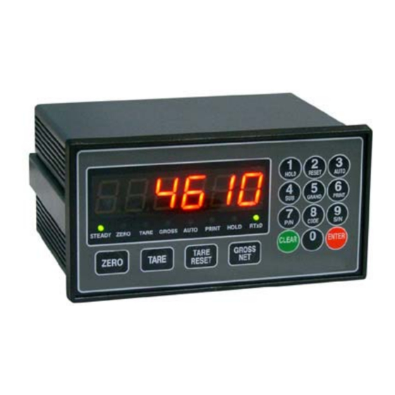
- Page 6 DIGITAL INDICATOR DN500N 3. DISPLAY (DISPLAY & KEY BOARD PART) 3-1. STATUS LAMP (▼) · STEADY : Lamp is on when weight is stable. · ZERO : Lamp is on when weight is “0”. · TARE : Lamp is on when tare weight is subtracted.
- Page 7 DIGITAL INDICATOR DN500N 3-2. KEY OPERATION - This key returns the display to the center of zero. Available within 2%, 5%, 10%, 20%, 100% of maximum capacity. - This key is used to subtract tare weight. - This key is used to cancel tare subtraction.
- Page 8 DIGITAL INDICATOR DN500N ※ HIDDEN KEY You can change key number if you press the other key within 2 seconds after you press “CLEAR” Key. To display and change TIME To display and change DATE To delete SUBTOTAL PRINTER DATA...
- Page 9 DIGITAL INDICATOR DN500N 3-3. REAR PANEL ② ③ ① ④ ⑤ ⑥ -Power Switch : Power ON/OFF Switch ①POWER -Fuse : AC 250V 10A -AC IN : This product can be used in AC 85V ~ 265V since it uses SMPS power.
-
Page 10: Installation
DIGITAL INDICATOR DN500N 4. INSTALLATION 4-1. EXTERNAL DIMENSION & CUTTING SIZE (EXTERNAL SIZE ×mm) -
Page 11: Calibration
DIGITAL INDICATOR DN500N 5. CALIBRATION What is Calibration? This is to match the displayed numerical value and the actual weight value for displaying weight. 5-1. ZERO CALIBRATION “0” is a point to be a standard for displaying weight of indicator. - Page 12 DIGITAL INDICATOR DN500N Ⅰ. STEP 1 This step is to set the value of 1 division. (Unit of minimum display division) Here, “d” stands for Division and it indicates “the value of 1 division (Minimum division display)” This value change is shown in order of “01-02-05-10-20-50” each time 0 Key is pressed.
- Page 13 DIGITAL INDICATOR DN500N Ⅴ. STEP 5 This span is to display the calculated Span constant. If indicator displays this condition, it means Span calculation is finished. If constant value is between 0.50000~1.50000, span is normally calibrated. If constant value is not between 0.50000~1.50000, you need to do the Span calibration once again so that you can use the scale with better accuracy.
- Page 14 DIGITAL INDICATOR DN500N 5-3. Error Display and Troubleshooting MESSAGE CAUSE SOLUTION - Please re-input the value of Max display It is displayed when Max. display division and one division so that Max. display Err 01 division/value of one division is...
-
Page 15: Set-Up
DIGITAL INDICATOR DN500N 6. SET-UP 6-1. SET-UP ●SUMMARY It is to set F-FUNCTION properly according to the actuator of scale and surroundings so that the scale can be operated on the optimized condition. ▶ ENTERING SET-UP When Power is OFF, please keep pressing “3” Key, and then Power will be ON and the main display will show “TEST”. - Page 16 DIGITAL INDICATOR DN500N ▶ HOW TO CHANGE SETTING FOR F-Function To change setting for F-Function, you need to ender the number you want with number Key and press “ENTER” Key so that it will be saved in the internal Memory and the change is completed.
- Page 17 DIGITAL INDICATOR DN500N 6-2. F-FUNCTION LIST F-Function DESCRIPTION DIVISION Divided into “CLR” and Input “ENTER” Select Set-Up&Calibration Set the location of decimal Point 0, 0.0, 0.00, 0.000 Normal(0), Back – UP(1) Zero Memory Mode. MOTION BAND Range 0, 1, 2, 3...
- Page 18 DIGITAL INDICATOR DN500N (● Factory Default) SET LOCATION OF DECIMAL POINT No Decimal Point One decimal place ● Two decimal places 0.00 Three decimal places 0.000 ZERO MEMORY MODE ● Normal Mode Back-up Mode * On normal condition, it doesn’t remember the weight on scale if power failure or Power OFF.
- Page 19 DIGITAL INDICATOR DN500N SET AUTO-ZERO RANGE It returns the displayed value to “0” when the weight is less than ∫ setting value and steady. ※ With this mode, you can automatically set “Zero” without pressing “Zero” Key before you do measuring again.
- Page 20 DIGITAL INDICATOR DN500N EXTERNAL INPUT Section ● ZERO Tare Remove Tare Print ZERO Tare/Remove Tare Hold Cancel Hold ZERO Tare/Remove Tare Subtotal Print ZERO Hold Cancel Hold Print ZERO Subtotal Total Print APPOINT CODE NUMBER ● Fixed increased 1 by each measuring work...
- Page 21 DIGITAL INDICATOR DN500N ※ SERIAL I/F SERIAL COMMUNICATION : PARITY BIT SETTING ● No Parity Odd Parity Even Parity SERIAL COMMUNICATION : SELECT COMMUNICATION SPEED 115,200 bps 76,800 bps 57,600 bps 38,400 bps 28,800 bps 19,200 bps 14,400 bps 9,600 bps ●...
- Page 22 DIGITAL INDICATOR DN500N ※ CENTRONICS PARALLEL OUT (PRINTER I/F) SET WEIGHING UNIT PRINT ● SELECT DATA OUTPUT IN CASE OF AUTO PRINT Automatic print is operated when weight is less than the setting ● value of F80 (near Zero) and increased again to be steady.
- Page 23 DIGITAL INDICATOR DN500N PRINT DELAY TIME Set print delay time from 0.1 to 9.9 sec ∫ 0.0 sec: No use for print delay time SET KEY TARE OPERATION ● Key Tare No Use Key Tare Use Available FUNCTION AUTO SETTING This is to automatically set the setting value of Function to the initial factory default..
- Page 24 DIGITAL INDICATOR DN500N CONFIRM & CHANGE DATE (YEAR, MONTH, DATE) You can confirm or change current date. CONFIRM & CHANGE TIME (HOUR, MINUTE, SECOND) You can confirm or change current time.
-
Page 25: Interface
DIGITAL INDICATOR DN500N 7. INTERFACE 7-1. Serial Interface RS-232C Serial Interface ● RS-232C Interface is sensitive to electric noise.. Therefore, please do the wiring separately from the wires of AC Power Cable or other electric wires and you must use Shield Cable for it. - Page 26 DIGITAL INDICATOR DN500N ▶ Data on number - 2B (H): "+"PLUS - 2D (H): "-"MINUS - 2O (H): " "SPACE - 2E (H): "."Decimal point ▶ UNIT ⑨Data format(2) Lamp Status Data(8) Blank Header1 Header2 ID NO. unit ▶ Header 1...
- Page 27 DIGITAL INDICATOR DN500N ▶Connection to PC (Personal Computer) and other devices 3: TxD RxD : 2 2: RxD TxD : 3 5: SG SG : 5 PERSONAL COMPUTER INDICATOR 9 PIN(Standard) ▶RS-232C Circuit 2. RxD 3. TxD 5. SG...
- Page 28 DIGITAL INDICATOR DN500N 7-2 Current Loop Interface Current Loop Interface is stronger than RS232C against electric noise. Therefore, it is more suitable for medium distance transmit. (about100M) ▶ Transmission Mode Same as RS232C ▶ Signal Format Same as RS232C 20mA ▶...
- Page 29 DIGITAL INDICATOR DN500N 7-3. RS-422 Series Communication (Option 04) RS-422 is to transmit signal by voltage difference. Therefore, it is more stable than other communication methods against electric noise. Please do wiring separately from AC Power Cable and other electric wires. Also you must use exclusive Shield Cable(over 0.5Φ) for communication.
- Page 30 DIGITAL INDICATOR DN500N ▶ COMMAND MODE ( READ COMMAND ) TO → INDICATOR COMMAND DESCRIPTION INDICATOR RESPONSE Command to transmit Time Transmit Time DATA(6) RTIM STX ID. NO. BCC ETX data of indicator RTIM 000000 STX ID.NO. BCC ETX Command to transmit Date...
- Page 31 DIGITAL INDICATOR DN500N ▶ COMMAND MODE ( WRITE COMMAND) TO → INDICATOR COMMAND DESCRIPTION INDICATOR RESPONSE WTAR ACK STX ID. NO. BCC ETX WTAR Command to set “TARE” STX ID. NO. BCC ETX WTAR NAK STX ID. NO. BCC ETX WTRS ACK STX ID.
- Page 32 DIGITAL INDICATOR DN500N WHOL ACK STX ID. NO. BCC ETX WHOL Command to set “HOLD” STX ID. NO. BCC ETX WHOL NAK STX ID. NO. BCC ETX WHRS ACK STX ID. NO. BCC ETX WHRS Command “HOLD RESET” STX ID. NO.
- Page 33 DIGITAL INDICATOR DN500N 7-4. PRINTER INTERFACE (Option 01) It is a serial Interface method and this method can be used for the connection to all printers communicated by this communication method. Print Format is programmed conforming to YJ-350(S/D, S/T). ▶ Connector Pin Assignment Pin No.
- Page 34 DIGITAL INDICATOR DN500N 7-5. ANALOG OUT(0~10V)INTERFACE(Option 02) This Option is to transmit display weight value by Voltage out to the external devices (such as Recoder, P.L.C Main Control etc.) controlled by analog signal. ▶ SPECIFICATIONS Output Voltage 0~10V DC Output...
- Page 35 DIGITAL INDICATOR DN500N 7-6. ANALOG OUT(4~20㎃)INTERFACE(Option 03) This Option is to transmit display weight value by Current out to the external devices (such as Recoder, P.L.C Main Control etc.) controlled by analog signal. ▶ SPECIFICATIONS 4~20㎃ for Available Range, Output Range is 2~22㎃...
- Page 36 DIGITAL INDICATOR DN500N - PRINTER SPECIFICATION - 1. Interface : RS232C Serial 2. Protocol : 9600 bps , No Parity, 8, 1 3. Column : 30 Column 4. Korean Font type : Combination Type 5. Emulation : EPSON TM-T88II GND1...
Need help?
Do you have a question about the DN500N and is the answer not in the manual?
Questions and answers