Advertisement
Available languages
Available languages
Quick Links
If you have any questions regarding assembly or if parts are missing, DO NOT return this item to the
store where it was purchased. Please call our customer service number and have your instructions and
parts list ready to provide the model name, part name or factory number:
Pacific Standard Time: 8:30 a.m. - 4:30 p.m., Monday - Friday
Or visit our web site 24 hours a day, 7 days a week for product assistance at
THIS INSTRUCTION BOOKLET CONTAINS IMPORTANT SAFETY INFORMATION.
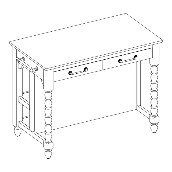
Harper Kitchen Island
Stock # PW1425004710045
ADULT ASSEMBLY REQUIRED
www.whalenstyle.com
Or e-mail your request to parts@whalenfurniture.com
PLEASE READ AND KEEP FOR FUTURE REFERENCE.
Date 2024-07-10
1-866-942-5362
Rev. 0001-A
LOT NUMBER:
DATE PURCHASED:
/
/
Advertisement

Subscribe to Our Youtube Channel
Related Manuals for Pioneer Woman Harper PW1425004710045


Summary of Contents for Pioneer Woman Harper PW1425004710045
- Page 1 LOT NUMBER: DATE PURCHASED: Harper Kitchen Island Stock # PW1425004710045 ADULT ASSEMBLY REQUIRED If you have any questions regarding assembly or if parts are missing, DO NOT return this item to the store where it was purchased. Please call our customer service number and have your instructions and parts list ready to provide the model name, part name or factory number: 1-866-942-5362 Pacific Standard Time: 8:30 a.m.
- Page 2 M A X I M U M R E C O M M E N D E D W E I G H T L O A D S MANUFACTURER: Whalen Furniture Manufacturing CATALOG : Harper Kitchen Island MODEL # PW1425004710045 MAXIMUM LOAD 90.7 kg / 200 lb.
- Page 3 Parts and Hardware List Please read completely through the instructions and verify that all listed parts and hardware are present before beginning assembly. A- Top Section (Qty. 1) B- Left Side Frame (Qty. 1) C- Right Side Frame (Qty. 1) D- Partition (Qty.
- Page 4 Assembly Instructions Nameplate Drawer removal Release lever NOTE: Please do not fully tighten all bolts and screws until you finish assembling all parts. Once assembled, go back and fully tighten all bolts and screws. This will make the assembly easier. 1.
- Page 5 Assembly Instructions ① x 4 ② x 4 ③ x 4 4. Align and attach the Right Side Frame (C) to the Top Section (A) using four 32 mm Bolts (1), four Lock Washers (2) and four Flat Washers (3). Tighten the bolts with the Ratchet Wrench provided.
- Page 6 Assembly Instructions The wood cleats will face the floor when the unit is turned upright. ① x 6 ② x 6 ③ x 6 5. Orient and attach two Open Shelves (E) to the Partition (D) by inserting six 32 mm Bolts (1) with the Washers (2 and 3) through the wood cleats and screw into place.
- Page 7 Assembly Instructions ① x 4 ② x 4 ③ x 4 6. Align and attach the assembled Open Shelves (E) to the Right Side Frame (C) using four 32 mm Bolts (1), four Lock Washers (2) and four Flat Washers (3).
- Page 8 Assembly Instructions ④ x 2 7. To hang your kitchen towels tidily, attach one Towel Holder / Side Handle (F) to the outside of Left Side Frame (B) with two 25 mm Bolts (4).
- Page 9 Assembly Instructions 3 2 1 ① x 8 ② x 8 ③ x 8 8. Align and attach the Left Side Frame (B) to the opposite side of previous assembly using eight 32 mm Bolts (1), eight Lock Washers (2) and eight Flat Washers (3).
- Page 10 Assembly Instructions ⑤ x 4 9. Install one Drawer Handle (G) to the front of each utility drawer with two 32 mm Handle Bolts (5).
- Page 11 Assembly Instructions 90° Nameplate Ball bearing cart FRONT FRONT Ball bearing cart Drawer installation 10. Ask for assistance to lift the assembled unit upright and position it near the final location. 11. Insert the removed drawers back into the frame by pushing the ball bearing cart all the way to the end of the slides (in both sides) and align the slide runners on the drawers with the slide tracks on the unit and push it carefully inside until it stops.
- Page 12 Assembly Instructions Wall Wooden stud Wall Metal bracket Long screw Short screw Connector Steel cable Floor leveler Tools required (not included): Phillips screwdriver, stud finder, tape measure, pencil, power drill and 1/8” drill bit. 12. Position the assembled unit at the desired location and adjust the pre-attached floor levelers at both Side Frames (B and C) to correct the tilting.
- Page 13 FURNITURE TIPPING RESTRAINT YOUNG CHILDREN MAY BE INJURED BY TIPPING FURNITURE AND YOU MUST USE THIS TIPPING RESTRAINT TO ATTACH THIS UNIT TO THE WALL, TO PREVENT ACCIDENTS AND/OR INJURIES. THIS HARDWARE, MUST BE PROPERLY INSTALLED (FOLLOW ALL DIRECTIONS IN ORDER ON THIS INSTRUCTIONS), TO PROVIDE PROTECTION AGAINST THE UNEXPECTED TIPPING OF FURNITURE DUE TO IMPROPER USE.
- Page 14 Care and Maintenance Use a soft, clean cloth that will not scratch the surface when dusting. Gently rub the surface with a soft dry cloth, soft damp cloth, or soft damp cloth with neutral detergent, and then dry it well. ...
- Page 15 NÚMERO de LOTE:__________ FECHA de COMPRA: Isla de cocina Harper Modelo # PW1425004710045 ENSAMBLE REQUERIDO POR ADULTO Si tienen alguna pregunta acerca del ensamble o si alguna parte está faltante, no retorne esté producto a la tienda donde lo compro. Por favor llame a nuestro departamento de ayuda al cliente teniendo su instructivo y lista de partes para proveer el modelo, nombre de parte o el número de fábrica: 1-866-942-5362 Hora estándar del Pacífico: 8:30 a.m.
- Page 16 M Á X I M O P E S O R E C O M E N D A D O FABRICANTE: Whalen Furniture Manufacturing CATALOGO : Isla de cocina Harper MODELO # PW1425004710045 CARGA MÁXIMA 90.7 kg / 200 lb. CARGA MÁXIMA 4.5 kg / 10 lb.
- Page 17 Lista de partes y material de ferretería Por favor lea completamente las instrucciones y verifique que estén todas las partes y partes de ferretería antes de iniciar el ensamblado A- Sección superior (Cant. 1) B- Marco izquierdo (Cant. 1) C- Marco derecho (Cant. 1) D- Divisor (Cant.
- Page 18 Instructivo de ensamble Placa de identificación Remover el cajón Placa de liberación NOTA: Por favor no apriete completamente todos los pernos, hasta que termine con el ensamble de las partes. Después asegúrese de apretar todos los pernos. Esto hará el ensamble más fácil. 1.
- Page 19 Instructivo de ensamble ① x 4 ② x 4 ③ x 4 4. Alinean y adjuntar el marco derecho (C) a la sección superior (A) usando cuatro pernos de 32 mm (1), cuatro arandelas de presión (2) y cuatro arandelas planas (3). Apretar los pernos con la llave trinquete provista.
- Page 20 Instructivo de ensamble Las molduras de madera apuntarán hacia el piso cuando esté en posición vertical. ① x 6 ② x 6 ③ x 6 5. Orientar y adjuntar 2 repisas abiertas (E) al divisor (D) insertando 6 pernos de 32 mm (1) con las arandelas (2 y 3) a través de los tacos de madera y atornillar en su lugar.
- Page 21 Instructivo de ensamble ① x 4 ② x 4 ③ x 4 6. Alinear y adjuntar las repisas abiertas ensambladas (E) al marco derecho (C) usando cuatro pernos de 32 mm (1), cuatro arandelas de presión (2) y cuatro arandelas planas (3).
- Page 22 Instructivo de ensamble ④ x 2 7. Para colgar sus toallas de cocina, adjuntar un soporte para toallas / manija lateral (F) a la parte exterior del marco izquierdo (B) con 2 pernos de 25 mm (4).
- Page 23 Instructivo de ensamble 3 2 1 ① x 8 ② x 8 ③ x 8 8. Alinear y adjuntar el marco izquierdo (B) al lado opuesto del ensamble previo usando 8 pernos de 32 mm (1), 8 arandelas de presión (2) y 8 arandelas planas (3).
- Page 24 Instructivo de ensamble ⑤ x 4 9. Instalar una manija para cajón (G) al lado frontal de cada cajón utilitario con 2 pernos para manija de 32 mm (5).
- Page 25 Instructivo de ensamble 90° Placa de identificación Carrito de baleros FRENTE FRENTE Carrito de baleros Instalación del cajón 10. Pedir asistencia para poner la unidad ensamblada en posición vertical y cerca del lugar final. 11. Insertar los cajones retirados de vuelta al marco empujando el carrito de baleros todo el camino al final de las correderas (en ambos lados), y luego alinear los complementos de corredera en los cajones con los carriles de corredera en la unidad y empujar hasta que tope.
- Page 26 Instructivo de ensamble Pared Viga de madera Pared Soporte de metal Perno largo Perno corto Conector Cable de acero Nivelador de piso Herramientas requeridas (no incluidas): Desarmador estrella, buscador de vigas, cinta métrica, lápiz, taladro y broca de 1/8 pulgadas. 12.
- Page 27 SISTEMA DE RESTRICCIÓN DE MOVIMIENTO NIÑOS PEQUEÑOS PUEDEN RESULTAR LASTIMADOS POR MUEBLES INCLINADOS Y DEBE INSTALAR EL JUEGO DE RESTRICCIÓN DE MOVIMIENTO CON LA UNIDAD EN FUNCIÓN, PARA PREVENIR LA INCLINACIÓN DE LA UNIDAD, CAUSANDO CUALQUIER ACCIDENTE O DAÑO. ESTÉ JUEGO DEBE SE INSTALADO CORRECTAMENTE (SIGA LAS DIRECCIÓN EN ORDEN DE LAS INSTRUCCIONES), PARA PROVEER PROTECCIÓN EN CONTRA DE LA INCLINACIÓN INESPERADA DEL MUEBLE DEBIDO AL USO INAPROPIADO.
- Page 28 Mantenimiento y cuidados Una toalla suave y limpia para evitar daños y rayaduras. Frotar gentilmente la superficie con una toalla suave y seca, una toalla suave y húmeda, o una toalla suave y húmeda con un detergente neutral, luego secar bien. ...
Need help?
Do you have a question about the Harper PW1425004710045 and is the answer not in the manual?
Questions and answers