Advertisement
Available languages
Available languages
Quick Links
If you have any questions regarding assembly or if parts are missing, DO NOT return this item to the
store where it was purchased. Please call our customer service number and have your instructions
and parts list ready to provide the model name, part name or factory number:
Pacific Standard Time: 8:30 a.m. - 4:30 p.m., Monday - Friday
Or visit our web site 24 hours a day, 7 days a week for product assistance at
THIS INSTRUCTION BOOKLET CONTAINS IMPORTANT SAFETY INFORMATION.
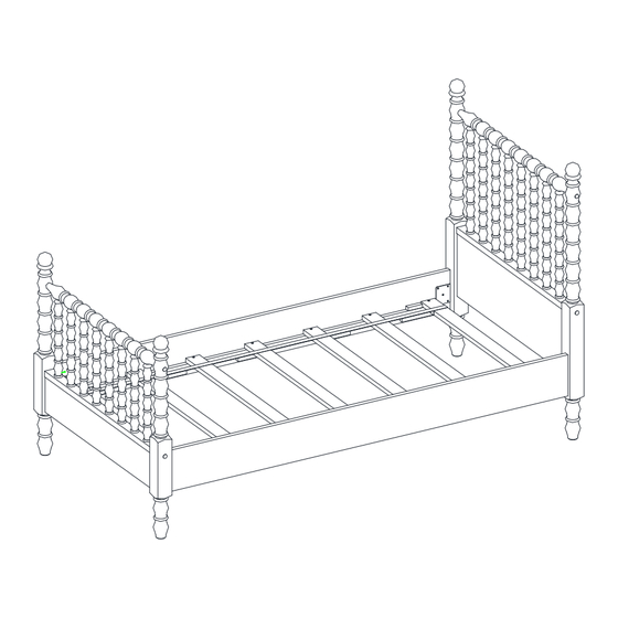
Twin Spindle Bed
Stock # PW1425004710047
# PW1425004710048
ADULT ASSEMBLY REQUIRED
www.whalenstyle.com
Or e-mail your request to parts@whalenfurniture.com
PLEASE READ AND KEEP FOR FUTURE REFERENCE.
Date 2024-05-28
1-866-942-5362
Rev. 0001-A
LOT NUMBER:
DATE PURCHASED:
/
/
Advertisement

Related Manuals for Pioneer Woman Harper PW1425004710047


Summary of Contents for Pioneer Woman Harper PW1425004710047
- Page 1 LOT NUMBER: DATE PURCHASED: Twin Spindle Bed Stock # PW1425004710047 # PW1425004710048 ADULT ASSEMBLY REQUIRED If you have any questions regarding assembly or if parts are missing, DO NOT return this item to the store where it was purchased. Please call our customer service number and have your instructions and parts list ready to provide the model name, part name or factory number: 1-866-942-5362 Pacific Standard Time: 8:30 a.m.
- Page 2 IMPORTANT Before you begin: Open, identify and count all parts prior to assembly. Lay out parts on a flat and non-abrasive surface. You will need the parts identified on page 3 and 4 of this instruction manuals. NOTE: IT IS VERY IMPORTANT TO USE GLUE WITH DOWELS. EXCESS GLUE CAN BE WIPED OFF WITH DAMP CLOTH.
- Page 3 Parts and Hardware List Please read completely through the instructions and verify that all listed parts and hardware are present before beginning assembly. A- Headboard Cross Assembly B- Footboard Cross Assembly (Qty. 1) (Qty. 1) C- Headboard Right Post D- Headboard Left Post (Qty.
- Page 4 Parts and Hardware List Please read completely through the instructions and verify that all listed parts and hardware are present before beginning assembly. (1) 5/16” x 38 mm Bolt (2) 5/16” x 56 mm Bolt (Qty. 12+1 extra) (Qty. 4+1 extra) (3) 5/16”...
- Page 5 Assembly Instructions ⑥ x 2 ① x 2 ④ x 2 ⑤ x 2 WARNING DO NOT fully tighten the bolts or screws initially until all the bolts or screws are ready to assemble. To avoid causing damages to the thread, DO NOT over-tighten the screws or bolts. 1.
- Page 6 Assembly Instructions ⑥ x 2 ① x 2 ④ x 2 ⑤ x 2 4. Repeat the same process to combine the Footboard Cross Assembly (B) and Footboard Panel (I) together.
- Page 7 Assembly Instructions ⑥ x 4 ① x 4 ④ x 4 ⑤ x 4 5. Glue four Wood Dowels (6) into the drilled holes of the Headboard Panel (H) at both ends. 6. Align and attach the assembled Headboard Panel (H) between the Headboard Posts (C and D) by inserting four 38 mm Bolts (1) with the Washers (4 and 5) through the wood cleats and securely screw into place.
- Page 8 Assembly Instructions ⑥ x 4 ① x 4 ④ x 4 ⑤ x 4 7. Repeat the same process to form the Footboard.
- Page 9 Assembly Instructions C/D/E/F ② x 4 ④ x 4 ⑤ x 4 8. Insert two 56 mm Bolts (2) with the Washers (4 and 5) through the upper countersunk holes on the Headboard Posts (C and D) and securely screw into the threaded inserts on the upper rail of the Headboard Cross Assembly (A).
- Page 10 ssembly Instructions C/D/E/F ④ x 4 ③ x 4 ⑤ x 4 10. Insert two 75 mm Bolts (3) with the Washers (4 and 5) through the lower countersunk holes on the Headboard Posts (C and D) and securely screw into the threaded inserts on the bottom rail of the Headboard Cross Assembly (A).
- Page 11 Assembly Instructions The solid strip is located at bottom and faces inward. Support surface 12. Ask for assistance to stand the assembled headboard upright and position it against wall and near the final location. 13. Pick up one Mattress Side Rail (G) and insert the metal hook into the slot of the Headboard Left Post (D) as shown.
- Page 12 Assembly Instructions 15. Follow steps 13-14 to attach the Footboard Posts (E and F) at the other end of the Mattress Side Rails (G).
- Page 13 Assembly Instructions ⑦ x 14 16. Lay out the Mattress Support Slats (J) onto the strips on both Mattress Side Rails (G). Make sure that the end slats are located close to the metal hooks. 17. Insert and screw the 25 mm Screws (7) into the countersunk holes on each slat. Tighten the screws with a Phillips screwdriver (not provided).
- Page 14 Assembly Instructions Floor leveler 18. Adjust the floor levelers pre-attached at the bottom of the Posts (C, D, E and F) until the unit is leveled.
- Page 15 Assembly Instructions C/D/E/F ⑧ x 8 19. Insert eight Wood Plugs (8) into the countersunk holes on the Posts (C, D, E and F). To prevent choking hazard, use a rubber mallet (not provided) to tamp in the wooden plugs to secure them. 20.
- Page 16 Care and Maintenance Use a soft, clean cloth that will not scratch the surface when dusting. Use of furniture polish is not necessary. Should you choose to use polish, test first in an inconspicuous area. Using solvents of any kind on your furniture may damage the finish. ...
- Page 17 NÚMERO de LOTE:__________ FECHA de COMPRA: Cama Torneada Individual Serie # PW1425004710047 # PW1425004710048 ENSAMBLE REQUERIDO POR ADULTO Si tienen alguna pregunta acerca del ensamble o si alguna parte está faltante, no retorne esté producto a la tienda donde lo compro. Por favor llame a nuestro departamento de ayuda al cliente teniendo su instructivo y lista de partes para proveer el modelo, nombre de parte o el número de fábrica: 1-866-942-5362 Hora estándar del Pacífico: 8:30 a.m.
- Page 18 Importante Antes de comenzar: Abra, identifique y cuente todas las partes antes del ensamble. Coloque las piezas sobre una superficie plana y no abrasiva. Tendrá las partes identificadas en la página 4 de este manual de instrucciones. NOTA: ES MUY IMPORTANTE EL USO DE GOMA CON LAS CLAVIJAS DE MADERA. EL. EXCESO DE PEGAMENTO SE PUEDE LIMPIAR CON UN PAÑO HÚMEDO.
- Page 19 Lista de partes y material de ferretería Por favor lea completamente las instrucciones y verifique que estén todas las partes y partes de ferretería antes de iniciar el ensamblado. A- Ensamble de la cabecera B- Ensamble de piecera (Cant. 1) (Cant.
- Page 20 Lista de partes y material de ferretería Por favor lea completamente las instrucciones y verifique que estén todas las partes y partes de ferretería antes de iniciar el ensamblado. (1) Perno de 5/16 de pulgada x 38 mm (2) Perno de 5/16 de pulgada x 56 mm (Cant.
- Page 21 Instructivo de ensamble ⑥ x 2 ① x 2 ④ x 2 ⑤ x 2 ADVERTENCIA NO apretar completamente los pernos o tuercas inicialmente hasta que los pernos o tuercas estén listos para ensamblar. Para evitar daños a la rosca, NO sobre apretar los pernos o tuercas. 1.
- Page 22 Instructivo de ensamble ⑥ x 2 ① x 2 ④ x 2 ⑤ x 2 4. Repetir el mismo proceso para combinar el ensamble de piecera (B) y el panel de piecera (I).
- Page 23 Instructivo de ensamble ⑥ x 4 ① x 4 ④ x 4 ⑤ x 4 5. Pegar cuatro clavijas de madera (6) en los agujeros perforados en el panel de la cabecera (H) en ambos extremos. 6. Alinear y adjuntar el panel de la cabecera ensamblado (H) entre los postes de la cabecera (C y D) insertando cuatro pernos de 38 mm (1) con las arandelas (4 y 5) a través de los soportes de madera y atornillar en su lugar.
- Page 24 Instructivo de ensamble ⑥ x 4 ① x 4 ④ x 4 ⑤ x 4 7. Repetir el mismo proceso para formar la piecera.
- Page 25 Instructivo de ensamble C/D/E/F ② x 4 ④ x 4 ⑤ x 4 8. Insertar 2 pernos de 56 mm (2) con las arandelas (4 y 5) a través los agujeros avellanados superiores en los postes de la cabecera (C y D) y atornillar en los insertos roscados en el riel superior del ensamble de la cabecera (A).
- Page 26 Instructivo de ensamble C/D/E/F ④ x 4 ③ x 4 ⑤ x 4 10. Insertar 2 pernos de 75 mm (3) con las arandelas (4 y 5 a través los agujeros avellanados inferiores en los postes de la cabecera (C y D) y atornillar en los insertos roscados en el riel inferior del ensamble de la cabecera (A).
- Page 27 Instructivo de ensamble El soporte sólido está en la parte inferior y apunta hacia adentro. Superficie de soporte 12. Pedir asistencia para levantar la cabecera ensamblada en posición vertical y contra de la pared y cerca del lugar final. 13. Tomar un riel lateral del colchón (G) e insertar el gancho de metal en el espacio del poste izquierdo de la cabecera (D) como se muestra.
- Page 28 Instructivo de ensamble 15. Siga los pasos 13 y 14 para adjuntar los postes de piecera (E y F) al otro extremo de los rieles laterales del colchón (G).
- Page 29 Instructivo de ensamble ⑦ x 14 16. Descansar las tablillas de soporte del colchón (J) sobre las franjas en ambos rieles laterales del colchón (G). Asegurar que las tablillas finales estén cerca de los ganchos de metal. 17. Insertar y atornillar los pernos de 25 mm (7) en los agujeros avellanados en cada tablilla. Apretar los pernos con el desarmador estrella (no provisto).
- Page 30 Instructivo de ensamble Nivelador de piso 18. Ajustar los niveladores de piso preguntados en la parte inferior de los postes (C, D, E y F) hasta que la unidad esté nivelada.
- Page 31 Instructivo de ensamble C/D/E/F ⑧ x 8 19. Insertar 8 tapones de madera (8) en los agujeros avellanados en los postes (C, D, E y F). Para prevenir el riesgo de asfixia, usar el mazo de goma (no provisto) para meter los tapones de madera para asegurar. 20.
- Page 32 Mantenimiento y cuidados Use una toalla suave y limpia para evitar daños y rayaduras. Uso de cera para pulir muebles no es necesario. Si desea usar cera, pruébela en un área que no sea visible para revisar su funcionamiento. ...
Need help?
Do you have a question about the Harper PW1425004710047 and is the answer not in the manual?
Questions and answers