
Subscribe to Our Youtube Channel
Related Manuals for nilan VPM 120


Summary of Contents for nilan VPM 120
- Page 1 User manual CTS 600 by Nilan VPM 120 VPM 240 VPM 480 VPM 560 VPL 28 Version: 6.00, 12-03-2012 Software-version: 1.38...
- Page 2 Table of contents Table of contents ..........................2 Figure table ............................ 2 Introduction ............................. 3 Types of units ..........................4 Review of the thermometer sensors ....................5 CTS 600 panel ..........................6 How to use the menu: ......................... 6 Review of the menus ........................7 Menus in the CTS 600 control .....................
- Page 3 Introduction Please control that the following documents have been delivered together with the unit: Directions for assembly and use CTS 600 directions (this document) Electrical chart The purpose of this manual is to clearly show the menus and possibilities of the CTS 600 control. This manual may describe functions that are not accessible in your unit.
- Page 4 The above figure shows the respective options of each model. The cooling option is achieved by installing a four-way valve that renders is possible to turn the process from heating to cooling. VPM 120 VPM 240 VPM 360 VPM 480...
- Page 5 Review of the thermometer sensors Figure 2: Thermometer sensors Explanation for figure 2: T1 - is the thermometer sensor for the fresh air and should be placed at the north side of the building. - is the thermometer sensor for the inlet air at the fan (without heating surface). - shows the temperature of the condenser.
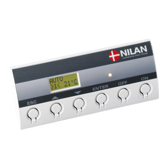
- Page 6 CTS 600 panel Use of t he CTS 600 panel : - pr ess ESC t o go one st ep back i n t he m enu - pr ess qpt o m ove up or down i n a m enu or t o adj ust an act i vat ed m enu - pr ess ENTER t o act i vat e a m enu - pr ess ENTER t o conf i r m a m enu...
- Page 7 Review of the menus Menus in the CTS 600 control CTS 600 control has 12 menus. The control will have the main menu as starting point, (the menu in the full-drawn frame). From here it is possible to go through the other menus via pq. SHOW Alarm display and reset.
- Page 8 Operating mode The main menu shows 3 different values: operating mode, ventilation step and temperature. Those values indicate the state of the unit and are selected by the user. The main menu is automatically shown 15 seconds after the unit is electrically connected and is now ready to be set.
- Page 9 Main menu The main menu is automatically shown 15 seconds after the unit is electrically connected. ” ” indicates that the menu point flashes and can be set to another value. Use of t he CTS 600 panel : - pr ess ESC t o go one st ep back i n t he m enu - pr ess qpt o m ove up or down i n a m enu or t o adj ust an act i vat ed m enu - pr ess ENTER t o act i vat e a m enu...
- Page 10 Show alarms If the unit is in a state of alarm the yellow light-emitting diode on the front of the CTS 600 panel will flash. The ”Show alarms” menu indicates the type of alarm and the time of the alarm. This is also the menu where the alarm should be reset.
- Page 11 Alarm codes are given because of a fault situation or when it is important to inform the user. The alarms are divided into the following categories: C Critical Operation is partly or completely stopped as long as the alarm is active. W Warning These types of alarms will become critical if the problem is not solved quickly.
- Page 12 Alarm Categori Text in Description/ cause How to remedy alarms code display ROOM LOW When room temperature drops Heat up the house and below 10°C the unit will stop in reset the alarm order to protect the house from further cooling down. The function is useful when the house is not occupied and the main heating has stopped.
- Page 13 Show data The actual operation data can be read in the ”Show data” menu. See review of thermometer sensors at page 5. ENTER SHOW STATUS DATA HEAT Room temperature recorded by T15 (sensor in CTS 600 PANEL control panel). T15 20°C T 10 is an external sensor that can be installed in an outlet...
- Page 14 User select The menu CUSTOM OPTIONS overrides the operating mode of the main menu by activating an external switch. There are four custom options: ”exhaust” and ”inlet”, ”extend” and “OFF” ”exhaust” and ”inlet”: These two options increase or reduce the velocity of the exhaust or inlet air respectively for a lim- ited period of time.
- Page 15 Setting of clock In case of power cut the clock will function for at least 24 hours. If the time function is lost there will be a alarm. Changing to daylight saving time has to be done manually. ” ” indicates that the menu point flashes and can be set to another value. Use of t he CTS 600 panel : - pr ess ESC t o go one st ep back i n t he m enu - pr ess qpt o m ove up or down i n a m enu or t o...
- Page 16 Week programme The unit is equipped with 3 standardized week programmes. See page 17. Anlægget er fra fabrikken indstillet til program 1. In addition to these programmes it is possible to programme your own week programme which can be one of the standard programmes with minor alterations. ”...
- Page 17 Factory settings for the 3 weekly programs: Program 1 is suitable for the working family Program 2 is suitable for the non-working family Program 3 is suitable for offices Program Week day Function Time Ventilation Temperature Program 1 Monday - 6.00 Friday 8.00...
- Page 18 Heating surface The menu HEATING SURFACE is only accessible when the system has a heating surface in- stalled and when the control has been set up to a heating surface in the SERVICE MENU. ” ” indicates that the menu point flashes and can be set to another value. Use of t he CTS 600 panel : - pr ess ESC t o go one st ep back i n t he m enu - pr ess qpt o m ove up or down i n a m enu or t o...
- Page 19 Cooling The ”Cooling” menu enables you to chose at which temperature cooling should be activated ac- cording to the room temperature. ” ” indicates that the menu point flashes and can be set to another value. Use of t he CTS 600 panel : - pr ess ESC t o go one st ep back i n t he m enu - pr ess qpt o m ove up or down i n a m enu or t o adj ust an act i vat ed m enu...
- Page 20 Air exchange In the ”Air exchange” menu it is possible to chose between 2 different types of ventilation depend- ing on your individual demand. ” ” indicates that the menu point flashes and can be set to another value. Use of t he CTS 600 panel : - pr ess ESC t o go one st ep back i n t he m enu - pr ess qpt o m ove up or down i n a m enu or t o adj ust an act i vat ed m enu...
- Page 21 Air filter In the ”Air filter” menu it is possible to chose the interval of the filter guard. The unit is factory configured to provide emergency with 90 days interval. It is then possible to change this range if necessary. ”...
- Page 22 Temp. control In the ”Temp. control” menu it is possible to set the highest and lowest inlet temperature. ” ” indicates that the menu point flashes and can be set to another value. Use of t he CTS 600 panel : - pr ess ESC t o go one st ep back i n t he m enu - pr ess qpt o m ove up or down i n a m enu or t o adj ust an act i vat ed m enu...
- Page 23 Setting of language In this menu you set which language to be used in the CTS 600 panel. ” ” indicates that the menu point flashes and can be set to another value. Use of t he CTS 600 panel : - pr ess ESC t o go one st ep back i n t he m enu - pr ess qpt o m ove up or down i n a m enu or t o adj ust an act i vat ed m enu...
- Page 24 System dimensions Connection to air heater Condensation drain Recommeded service distance Service-distance Figure 18: Dimensions VPM 120 1.975 1.000 Ø315 VPM 240 2.155 1.240 1.200 Ø400 VPM 360 2.255 1.400 1.200 Ø500 VPM 120 2.976 1.975 VPM 240 3.260 2.155 VPM 360 3.360...
- Page 25 Accessories/spare parts VPM 120 Filter System type Qty. Nilan Item no. F5 (Standard in outlet) HI-FLO 490x392–4x380–40 3948 F7 (Standard in inlet) HI-FLO 490x392–8x380–85 3949 VPM 240 Filter System type Qty. Nilan Item no. F5 (Standard in outlet) HI-FLO 592x490–6x380–40...
- Page 26 Vibration absorber System System type Qty. Nilan Item no. VPM 120 Sylomer (Green) 3045 VPM 240 Sylomer (Brown) 3046 VPM 360 Sylomer (Brown) 3046 VPM 480 Sylomer (Brown) 3046 VPM 560 Sylomer (Brown) 3046 VPL 28 Sylomer (Green) 30451 Heating cable for condensation outlet (frost protection)
Need help?
Do you have a question about the VPM 120 and is the answer not in the manual?
Questions and answers