nilan CTS 602 User Manual
Hide thumbs
Also See for CTS 602:
- User manual ,
- Installation instructions manual (48 pages) ,
- Manual (40 pages)

Related Manuals for nilan CTS 602


Summary of Contents for nilan CTS 602
- Page 1 User manual CTS 602 by Nilan VP 18 EK Version: 10.00, 13-04-2015 Software-version: 2.30...
-
Page 2: Table Of Contents
Review of the thermometer sensors ....................5 CTS 602 panel ..........................6 How to use the menu: ......................... 6 Review of the menus ........................7 Menus in the CTS 602 control ..................... 7 Operating mode ..........................8 Main menu ..........................9 Show alarms ..........................10 Show data .......................... -
Page 3: Introduction
CTS 602 directions (this document) Electrical chart The purpose of this manual is to clearly show the menus and possibilities of the CTS 602 control. The manual may contain functions and facilities which are not available on your system. Unless otherwise stated in the titles, the descriptions apply to all systems listed on page 4. -
Page 4: Types Of Units
Types of units The control is made for the following ventilation units. VP18 M2 EK Figure 1: Types of units page 4 af 33 May be subject to change... -
Page 5: Review Of The Thermometer Sensors
T14: is the temperature in the boiler T15: is the thermometer sensor in the CTS 602 panel. The temperature of the sensors can be read in the “Show data” menu. page 5 af 33 May be subject to change... -
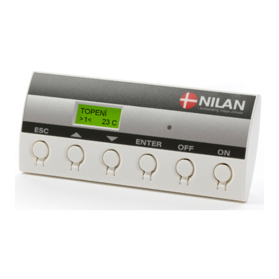
Page 6: Cts 602 Panel
Figure 3: CTS 602 panel The following is indicated by the light-emitting diode at the front of the CTS 602 panel: Constant yellow light: the compressor is in operation Flashing yellow: the unit is in alarm condition The panel can show 2 lines of text with each 8 characters. -
Page 7: Review Of The Menus
Review of the menus Menus in the CTS 602 control CTS 602 control has 12 menus (if the unit is with cooling). The control will have the main menu as starting point, (the menu in the full-drawn frame). From here it is possible to go through the other menus via pq. -
Page 8: Operating Mode
Operating mode The main menu shows 3 different values: operating mode, ventilation step and temperature. Those values indicate the state of the unit and are selected by the user. The main menu is automatically shown 15 seconds after the unit is electrically connected and is now ready to be set. -
Page 9: Main Menu
Main menu The main menu is automatically shown 15 seconds after the unit is electrically connected. ” ” indicates that the menu point flashes and can be set to another value. The options available on the main menu are shown in the figure below: Use of the CTS602 panel: - press ESC to go one step back in the menu... -
Page 10: Show Alarms
Show alarms If the unit is in a state of alarm the yellow light-emitting diode on the front of the CTS 602 panel will flash. The ”Show alarms” menu indicates the type of alarm and the time of the alarm. This is also the menu where the alarm should be reset. - Page 11 Alarm codes are given because of a fault situation or when it is important to inform the user. The alarms are divided into the following categories: C Critical Operation is partly or completely stopped as long as the alarm is active. W Warning These types of alarms will become critical if the problem is not solved quickly.
- Page 12 Alarm Categori Text in Description/ cause How to remedy alarms code display ROOM LOW When room temperature drops Heat up the house and below 10°C the unit will stop in reset the alarm order to protect the house from further cooling down. The function is useful when the house is not occupied and the main heating has stopped.
-
Page 13: Show Data
HEATING Anode condition OK, ERROR or SERVICE ANODE PANEL T15 20°C Roomt emperature EXTERNAL at T15 (sensor in T10 20°C CTS 602-panelet) INLET 25°C FRESH AIR 20°C WATER T T11 50°C The location of the thermometer WATER B sensors are shown T12 40°C... -
Page 14: User Select 1 And 2
User select 1 and 2 In the ”User select” menu it is possible to overrule the operation mode in the main menu. It is possible to e.g. increase the speed of the exhaustion for a limited period of time. If the ventilation step and/or temperature is being adjusted in the main menu any active user selec- tions are deleted. -
Page 15: Setting Of Clock
Setting of clock In case of power cut the clock will function for at least 24 hours. If the time function is lost there will be a alarm. Changing to daylight saving time has to be done manually. ” ” indicates that the menu point flashes and can be set to another value. Use of the CTS602 panel: - press ESC to go one step back in the menu... -
Page 16: Week Programme
Week programme The unit is equipped with 3 standardized week programmes. Anlægget er fra fabrikken indstillet til program 1. In addition to these programmes it is possible to programme your own week programme which can be one of the standard programmes with minor alterations. ”... -
Page 17: Factory Settings For The 3 Weekly Programs
Factory settings for the 3 weekly programs: Program 1 is suitable for the working family Program 2 is suitable for the non-working family Program 3 is suitable for offices Program Week day Function Time Ventilation Temperature Program 1 Monday - 6.00 Friday 8.00... -
Page 18: Central Heating
Central heating Settings for boiler control are displayed in the CENTRAL HEATING menu. The values shown are recommended values. Options that flash are indicated by ” ”. ”DEMAND” will stop the EK- ENTER MODE module when there is a high ”DEMAND”... - Page 19 Boiler function Additional descriptions of the boiler function for the VP18 M2 EK CTS602. Operating mode There are three different operating modes: Operating Boiler status Tforward motion Circulating Heat pump mode determined by pump None Off, but with active On, water for do- antiseize.
- Page 20 Curve control The forward motion temperature is regulated automatically in accordance to a curve. See the dia- gram below: Curve control Central heating temperature Max. temperature Displace Max. temperature Outdoor temperatur Summer mode The forward motion temperature is controlled as a function by the outdoor temperature so that the forward motion temperature depends on the outdoor temperature.
- Page 21 Delay This function is used for demand-control. In extension of the description above, this menu deter- mines how long a deviation of the wanted room temperature can take place before the boiler is started. Pump It is possible to choose between two adjustments of the circulating pump for the central heating system.
- Page 22 Hot water The ”Hot water” menu shows the data for production of hot water. ” ” indicates that the menu point flashes and can be set to another value. Use of the CTS602 panel: - press ESC to go one step back in the menu - press qp to move up or down in a menu or to adjust an activated menu...
-
Page 23: Cooling
Cooling The menu COOLING can only be accessed in the control panel when the system is a VP 18 Cool- The ”Cooling” menu enables you to chose at which temperature cooling should be activated ac- cording to the room temperature. ”... -
Page 24: Air Exchange
Air exchange In the ”Air exchange” menu it is possible to chose between 3 different types of ventilation depend- ing on your individual demand. ” ” indicates that the menu point flashes and can be set to another value. Use of the CTS602 panel: - press ESC to go one step back in the menu - press qp... -
Page 25: Air Filter
Air filter In the ”Air filter” menu it is possible to chose the interval of the filter guard. The interval is preset to a 90 day interval. ” ” indicates that the menu point flashes and can be set to another value. Use of the CTS602 panel: - press ESC to go one step back in the menu... -
Page 26: Temp. Control
Temp. control In the ”Temp. control” menu it is possible to set the highest and lowest inlet temperature. ” ” indicates that the menu point flashes and can be set to another value. Use of the CTS602 panel: - press ESC to go one step back in the menu - press qp to move up or down in a menu or to adjust an... -
Page 27: Setting Of Language
Setting of language In this menu you set which language to be used in the CTS 602 panel. ” ” indicates that the menu point flashes and can be set to another value. Use of the CTS602 panel: - press ESC... -
Page 28: Faultfinding
If there should be any operating errors please inspect the following before contacting your service mechanic: Check if the alarm diode on the CTS 602 panel is flashing. If this is the case please read the alarm in the “Show alarms” menu and correct the fault. If necessary please contact your local service mechanic. -
Page 29: Maintenance
The filters should be cleaned and renewed when needed. Usually the filters need to be re- newed once a year. The filter guard in the CTS 602 control can be used in order to make sure that the filters are checked. Please see CTS 602 directions for further information. (delivered together with the VP18). - Page 30 Once a year: The sacrificial anode must be checked to ensure that monitoring of the anode is intact. (No.24) The wire marked with “yellow/green” is dismantled at the anode. This produces the “ALARM 70” (LED flashing) The wire marked with “yellow/green” is reassembled at the anode. “ALARM 70” (LED not flashing) The hot-water tank can corrode if the anode is left unchanged.
- Page 31 Austausch eines Ventilators: page 31 af 33 May be subject to change...
-
Page 32: Energy Saving
Energy saving Use the setting ”Energy” in the ”Air exchange” menu in the CTS 602 control. Please see CTS 602 directions for further information. (delivered together with the VP18). Keep the hot-water at a low temperature. Try with 45°C. The auxiliary heating element should be cut off and only be used at very large hot-water demands. -
Page 33: Accessories
Nilan itemnr. Hygrostat 3637 CTS 602, control PCB 229933 CTS 602, control panel complete 2398 CTS 602, white control panel enclosure 2398HX Heating cable for condense outlet (frost protection) 2172 Sacrificial anode 5/4” MG ø33x450mm 19203 page 33 af 33...
Need help?
Do you have a question about the CTS 602 and is the answer not in the manual?
Questions and answers