nilan CTS 600 User Manual
Vpl 15;vpl 15 top;vpl 25
Hide thumbs
Also See for CTS 600:
- Installation instruction (23 pages) ,
- User manual (33 pages) ,
- User manual (26 pages)

Related Manuals for nilan CTS 600


Summary of Contents for nilan CTS 600
- Page 1 User manual CTS 600 by Nilan VPL 15 VPL 15 TOP VPL 25 Version: 5.01, 15-04-2011 Software-version: 1.36...
-
Page 2: Table Of Contents
Review of the thermometer sensors ....................5 CTS 600 panel ..........................6 How to use the menu: ......................... 6 Review of the menus ........................7 Menus in the CTS 600 control ..................... 7 Operating mode ..........................8 Main menu ..........................9 Show alarms ..........................10 Show data .......................... -
Page 3: Introduction
CTS 600 directions (this document) Electrical chart The purpose of this manual is to clearly show the menus and possibilities of the CTS 600 control. This manual may describe functions that are not accessible in your unit. The directions can be used for all types of units described in figure 1 page 4. -
Page 4: Types Of Units
Types of units The control is made for the following ventilation units. The above figure shows the respective options of each model. The cooling option is achieved by installing a four-way valve that renders is possible to turn the process from heating to cooling. VPL 15 VPL 15T VPL 25... -
Page 5: Review Of The Thermometer Sensors
- is the thermometer sensor for the inlet air after a heating surface. T10 - is the thermometer sensor for the exhaust air in a room (accessory). T15 - is the thermometer sensor in the CTS 600 panel. The temperature of the sensors can be read in the “Show data” menu. -
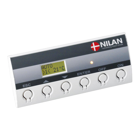
Page 6: Cts 600 Panel
- pr ess ON t o t ur n t he uni t on Figure 3: CTS 600 panel The following is indicated by the light-emitting diode at the front of the CTS 600 panel: Constant yellow light: the compressor is in operation Flashing yellow: the unit is in alarm condition The panel can show 2 lines of text with each 8 characters. -
Page 7: Review Of The Menus
Review of the menus Menus in the CTS 600 control CTS 600 control has 12 menus. The control will have the main menu as starting point, (the menu in the full-drawn frame). From here it is possible to go through the other menus via pq. -
Page 8: Operating Mode
Operating mode The main menu shows 3 different values: operating mode, ventilation step and temperature. Those values indicate the state of the unit and are selected by the user. The main menu is automatically shown 15 seconds after the unit is electrically connected and is now ready to be set. -
Page 9: Main Menu
” ” indicates that the menu point flashes and can be set to another value. Use of t he CTS 600 panel : - pr ess ESC t o go one st ep back i n t he m enu... -
Page 10: Show Alarms
Show alarms If the unit is in a state of alarm the yellow light-emitting diode on the front of the CTS 600 panel will flash. The ”Show alarms” menu indicates the type of alarm and the time of the alarm. This is also the menu where the alarm should be reset. - Page 11 Alarm codes are given because of a fault situation or when it is important to inform the user. The alarms are divided into the following categories: C Critical Operation is partly or completely stopped as long as the alarm is active. W Warning These types of alarms will become critical if the problem is not solved quickly.
- Page 12 Alarm Categori Text in Description/ cause How to remedy alarms code display SOFTWARE Error in software Contact service WATCHDOG Error in software Contact service CONFIG Parts of the programming are lost Reset alarm and can be caused by a longer Re-programme the week period of power failure or lightning.
-
Page 13: Show Data
See review of thermometer sensors at page 5. ENTER SHOW STATUS DATA HEAT Room temperature recorded by T15 (sensor in CTS 600 PANEL control panel). T15 20°C T 10 is an external sensor that can be installed in an outlet EXTERNAL fitting in the sitting 9°C... -
Page 14: User Select
Deactivates the external switch. Options that flash are indicated by ” ”. Use of t he CTS 600 panel : - pr ess ESC t o go one st ep back i n t he m enu - pr ess qpt o m ove up or down i n a m enu or t o... -
Page 15: Setting Of Clock
” ” indicates that the menu point flashes and can be set to another value. Use of t he CTS 600 panel : - pr ess ESC t o go one st ep back i n t he m enu... -
Page 16: Week Programme
” ” indicates that the menu point flashes and can be set to another value. Use of t he CTS 600 panel : - pr ess ESC t o go one st ep back i n t he m enu... -
Page 17: Factory Settings For The 3 Weekly Programs
Factory settings for the 3 weekly programs: Program 1 is suitable for the working family Program 2 is suitable for the non-working family Program 3 is suitable for offices Program Week day Function Time Ventilation Temperature Program 1 Monday - 6.00 Friday 8.00... - Page 18 ” ” indicates that the menu point flashes and can be set to another value. Use of t he CTS 600 panel : - pr ess ESC t o go one st ep back i n t he m enu...
-
Page 19: Cooling
” ” indicates that the menu point flashes and can be set to another value. Use of t he CTS 600 panel : - pr ess ESC t o go one st ep back i n t he m enu... -
Page 20: Air Exchange
” ” indicates that the menu point flashes and can be set to another value. Use of t he CTS 600 panel : - pr ess ESC t o go one st ep back i n t he m enu... -
Page 21: Air Filter
” ” indicates that the menu point flashes and can be set to another value. Use of t he CTS 600 panel : - pr ess ESC t o go one st ep back i n t he m enu... -
Page 22: Temp. Control
” ” indicates that the menu point flashes and can be set to another value. Use of t he CTS 600 panel : - pr ess ESC t o go one st ep back i n t he m enu... -
Page 23: Setting Of Language
Setting of language In this menu you set which language to be used in the CTS 600 panel. ” ” indicates that the menu point flashes and can be set to another value. Use of t he CTS 600 panel :... -
Page 24: System Dimensions
System dimensions Front view Right view Left view 1. Fresh air intake. 5. Compressor 9. Inlet fan 2. Exhaust 6. Condensator (hidden) 10. Exhaust fan 3. Inlet 7. Evaporator 11. Condensation drain 4. Discharge 8. Electrical connections Dimensions in mm: VPL 15 Ø160 Ø20... -
Page 25: Accessories / Spare Parts
Accessories / spare parts VPL 15 Filter types Qty. Nilan item no. F5 (exhaust) 3953 F7 (inlet) 3952 VPL 15T Filter types Size Antal Nilan item no. Filter for item no. 8481 Ø160mm 8504 T-filter, comlete Ø160mm 8481 VPL 25...
Need help?
Do you have a question about the CTS 600 and is the answer not in the manual?
Questions and answers