Advertisement
Quick Links
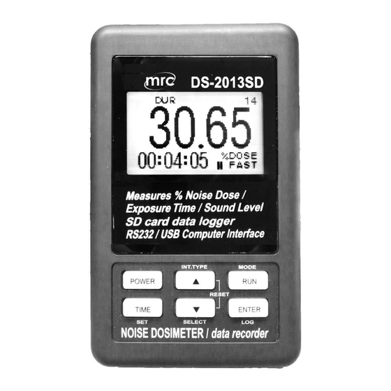
SD card real time datalogger, RS232/USB Frequency
weighting and Time weighting meet IEC 61672 class 2 ,
Personal sound exposure meet IEC 61252
Noise Dosimeter
Model : DS-2013SD
OPERATION MANUAL
PLEASE READ THIS MANUAL CAREFULLY BEFORE OPERATION
3, Hagavish st. Israel 58817
Tel: 972 3 5595252, Fax: 972 3 5594529
MRC. 3.21
Your purchase of this
Personal sound exposure
Noise Dosimeter
with SD CARD
DATALOGGER marks a
step forward for you
into the field of
precision measurement.
Although this METER is
a complex and delicate
instrument, its durable
structure will allow
many years of use if
proper operating
techniques are
developed. Please read
the following
instructions carefully
and always keep this
manual within easy
reach.
mrc@mrclab.com
Advertisement

Related Manuals for MRC DS-2013SD


Summary of Contents for MRC DS-2013SD
- Page 1 SD card real time datalogger, RS232/USB Frequency weighting and Time weighting meet IEC 61672 class 2 , Personal sound exposure meet IEC 61252 Noise Dosimeter Model : DS-2013SD Your purchase of this Personal sound exposure Noise Dosimeter with SD CARD...
- Page 2 TABLE OF CONTENTS 1. FEATURES......................2. SPECIFICATIONS....................3. FRONT PANEL DESCRIPTION................4. MEASURING PROCEDURE................4-1 Sound Pressure Level Measurements (SPL)......... 7 4-2 Running the Dose Meter Noise Survey (DOSE %)………………….. 8 4-3 Data Hold......................4-4 Data Record ( Max., Min. reading )................4-5 LCD Backlight ON/OFF…………………………………………………………………...
- Page 3 1. FEATURES Personal Noise Dosimeter/Datalogger * Frequency and Time weighting are designed to meet IEC 61672 class 2. * A & C weighting networks comply with standards. * LCD is dot-matrix with backlight and easy reading. * Combination Dose meter, Data-logger and Sound level meter. * 0.5"...
- Page 4 2. SPECIFICATIONS Circuit Custom one-chip of microprocessor LSI circuit. Display LCD size : 50 mm x 30 mm LCD with green backlight ( ON/OFF ). Measurement SPL : Sound pressure level Dose:test noise exprosure Type SPL:Auto 30 - 130 dB. Measurement Dose:70~130dB Range...
- Page 5 Frequency Characteristics of A & C. Weighting Network A weighting : The characteristic is simulated as "Human Ear Listing" response. Typical, if making the environmental sound level measurement, always select to A weighting. C weighting The characteristic is near the "FLAT" response.
- Page 6 Calibration VR Build in external calibration VR, easy to calibrate on 94 dB level by screw driver. * Calibrated via external SOUND CALIBRATOR ( SC-942, optional ). Calibrator B & K (Bruel & kjaer), MULTIFUNCTION ACOUSTIC CALIBRATOR Type 4226. Datalogger Auto 1 second to 3600 seconds Sampling Time...
- Page 7 Power off Auto shut off saves battery life or manual off by push button. 0 to 50 ℃. Operating Temperature Operating Less than 85% R.H. Humidity Power Supply * AC/DC power adapter is optional. Alkaline or heavy duty DC 1.5 V battery ( UM4, AAA ) x 6 PCs, or equivalent.
- Page 8 3. FRONT PANEL DESCRIPTION Fig. 1 3-1 Display. 3-11 Microphone input jack 3-2 Power Button( Backlight Button ) 3-12 External 94dB CAL. VR 3-3 ▲ Button ( Hold only for SPL ) 3-13 Reset Switch. 3-4 RUN Button ( REC only for SPL) 3-14 RS232 Output 3-5 TIME Button (Set) 3-15 SD card socket...
- Page 9 4. MEASURING PROCEDURE 4-1 Sound Pressure Measurements (SPL) In SPL mode the display shows readings of the sound pressure level. 1) Power ON the meter by pressing and holding the " Power Button " ( 3-2, Fig. 1 )for at least 1.5 seconds, the meter's default function is "...
- Page 10 4-2 Running the Dose Meter Noise Survey 1) In " SPL" mode to select the " Dose " mode by pressing and holding the" RUN button" ( 3-4 Fig 1 ) into the DOSE mode . 2) In "DOSE" mode, display will show DUR(duration) , 0.00(cumulative dose) , 00 : 00 :00(current time) , 0(record sampling time counter) , %DOSE(Dose mode) , FAST(Time weighting).
- Page 11 pressing and holding the ▲ button , display is shown and the BEG , x.xx , xx - xx : xx(date - hr : min) and then pressing and holding the ▼ button , display is shown and the BEG , xx - xx : xx(dd - h : m) and END xx - xx : xx(dd - h : m) , pressing ▲...
- Page 12 b) To exit the memory record function, just press the " RUN " button > 2 seconds at least. The display will revert to the current reading. 4-5 LCD Backlight ON/OFF After power ON, the " LCD Backlight " will light automatically.
- Page 13 5. DATALOGGER 5-1 Preparation before execute datalogger function a. Insert the SD card Prepare a " SD memory card " ( 1 GB to 16 GB, optional ), insert the SD card into the " SD card socket " ( 3-15, Fig. 1). The front panel of the SD card should face against the down case.
- Page 14 ≧ 5-2 Auto Datalogger ( Set sampling time 1 second ) a. Start the datalogger Pressing and holding the " ENTER Button "( 3-7, Fig. 1 ) once , display is shown " LOGGER " , the " LOGGER " will flashing at the same time the measuring data along the time information will be saved into the memory circuit(EEPROM).
- Page 15 d. Send the Datalogger Data EEPROM data send to SD card or RS232 select , press "▲ + RUN " Button continuously at least two seconds , the " SEND TO SD and RS232 " text will be appeared , use "▲ or ▼ "Button to select SD or RS232 , then press "...
- Page 16 5-5 SD Card Data structure 1) When the first time, the SD card is used into the meter, the SD card will generate a folder : SLD01 2) If the first time to execute the Datalogger, under the route SLD01\, will generate a new file name SLD01001.XLS.
- Page 17 6. Saving data from the SD card to the computer ( EXCEL software ) 1) After execute the Data Logger function, take away the SD card out from the " SD card socket " ( 3-15, Fig. 1 ). 2) Plug in the SD card into the Computer's SD card slot ( if your computer build in this installation ) or insert the SD card into the "...
- Page 18 EXCEL graphic screen ( for example )
- Page 19 7. ADVANCED SETTING Under do not execute the Datalogger function, press the " TIME Button " ( 3-5, Fig. 1 ) continuously at least 1.5 seconds will enter the " Advanced Setting " mode. then press the "TIME Button " (3-5, Fig. 1 ) once a while in sequence to select the eleven main function, the lower display will show : DATE……...
- Page 20 2) After set all the time value ( Year, Month, Date, Hour, Minute, Second ), the screen will jump to " Set sampling time character " setting screen ( Chapter 7-2 ). Remark : After the time value is setting, the internal clock will run precisely even Power is off ( The battery is under normal condition, no low battery condition ).
- Page 21 7-4 Set beeper sound ON/OFF When the lower display show " BEEP " 1) Use the " ▲ Button " ( 3-3, Fig. 1 ) or " ▼ Button " ( 3-6, Fig. 1 ) to select the upper text to " YES " or "...
- Page 22 2) After select the upper text to " USA " or " EURO ", press the " ENTER Button " ( 3-7, Fig. 1 ) will save the setting function with default. 7-6 SD memory card Format When the lower display show " SD-F " 1) Use the "...
- Page 23 Note : a. The characteristic table of A, C weighting, please ref. page 24. b. The characteristic of A weighting is simulated as the " Human Ear Listening " response. Typically always select the A weighting when makes environmental sound level measurement. c.
- Page 24 10. BATTERY REPLACEMENT 1) When the left corner of LCD display show " ", it is necessary to replace the battery. However, in-spec. measurement may still be made for several hours after low battery indicator appears before the instrument become inaccurate. 2) Loose the "...
- Page 25 The 16 digits data stream will be displayed in the following format : D15 D14 D13 D12 D11 D10 D9 D8 D7 D6 D5 D4 D3 D2 D1 D0 Each digit indicates the following status : Start Word When send the SPL display data = 1 When send the DOSE display data = 2 D12, D11 Annunciator for Display...
- Page 26 12. CALIBRATION 1) Prepare the optional " SOUND CALIBRATOR ", such as " SC-941 " or " SC-942 " ( set range to 94.0 dB ). Power on the Sound Calibrator & plug calibrator output socket into the " Microphone " head ( 3-8, Fig. 1 ) of the Sound Level meter.
- Page 27 14. TIME WEIGHTING ( F/S ) CHARACTERISTICS Max. response Tolerance Charac. ref. continuous ( IEC 61672 Class 2 ) signal F ( Fast ) - 1.0 dB + 1.0 dB , - 2.0 dB S ( Slow ) - 4.1 dB ±2.0 dB * Test under signal on 1,000 Hz/94 dB.
Need help?
Do you have a question about the DS-2013SD and is the answer not in the manual?
Questions and answers