
Related Manuals for Top Gun THOR-180


Summary of Contents for Top Gun THOR-180
- Page 1 Battery Powered Welder Battery Powered Welder User Manual User Manual LiFePO4 LiFePO4 180A 180A 623.7Wh 623.7Wh -10°C~60°C -10°C~60°C Quick Charging Quick Charging LK-160SF LK-160SF LK-180TF LK-180TF LK-180MF LK-180MF THOR-180...
- Page 2 Certification standards: PSE CE UN38.3 ROHS The relevant design schemes and manufacturing technology used in this product are protected by patents. The copyright of this manual is owned by Top Gun Welding Supplies. Its contents are subject to change without notice.
- Page 3 CONTENTS 1.Safety Tips And Precautions 2. Product Introduction 2.1 Appearance 2.2 Control Panel 2.3 LCD Screen Display 2.4 Technical Details 3.Instructions For Use 3.1 Turn On/Off Welder 3.2 Light Function 3.3 Charging Methods 3.4 MMA Mode 3.4.1 VRD MMA 3.5 TIG Mode 3.6 ESD Mode 3.6.1 SINGLE_ESD 3.6.2 TIMES_ESD...
- Page 4 SAFETY TIPS AND PRECAUTIONS SAFETY TIPS AND PRECAUTIONS SAFETY TIPS AND PRECAUTIONS SAFETY TIPS AND PRECAUTIONS SAFETY TIPS AND PRECAUTIONS Please keep this User Manual and read it carefully before use. This user manual describes how to use the equipment safely and e Please keep this User Manual and read it carefully before use.
- Page 5 1.5 Beware Of Arc Flash 1.5 Beware Of Arc Flash • Strong arc will be generated during welding. Therefore, a welding helmet r and cover should be used to 1.5 Beware Of Arc Flash • Strong arc will be generated during welding. Therefore, 1.5 Beware Of Arc Flash prevent the eyes from being hurt by sparks or arcs when welding a welding helmet...
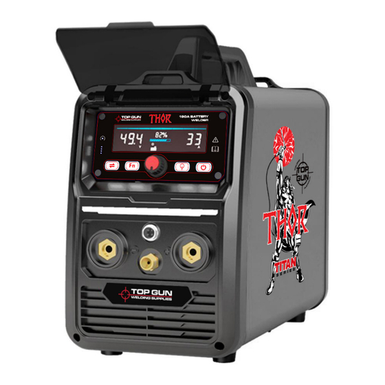
- Page 6 PRODUCT INTRODUCTION 2.1 Appearance Name Description Panel Cover Operational Panel Protection Control Panel See Control Panel for Details on its Functions Light Light Source DC - Connect to Negative Welding Cable DC + Connect to Positive Welding Cable Signal Port Connect to MIG &...
- Page 7 2.2 Control Panel 180A BATTERY WELDER Name Description Reset Icon Reset the product when the product crashes Upgrade Port Upgrade Firmware Version Mode Switch Button Switch MMA/TIG/ESD/MIG Mode *Long-press for 10 seconds to restore all modes to factory settings and power off the machine. Function Switch Function Selection *Long-press for 5 seconds to restore the current mode to default settings.
- Page 8 2.3 LCD Screen Display Icon means Set up Icon Initialization Icon Fan Icon Charging Icon Alarm Icon High Temperature Icon Low Temperature Icon 2T Mode Icon 4T Mode Icon VRD Mode Icon *W W hen enabled, no-load voltage output between 18~20V Current Icon Voltage Icon Voltage Icon...
- Page 9 Time Icon F F r r e e q q u u e e n n c c y y Icon P P e e r r c c e e n n t t Icon Wire Feeding Icon Wire Feeding Speed Icon Diameter Icon Length Icon Gas Cylinder Icon...
- Page 10 2.4 Technical Details Technical Specification Model LK-160SF, LK-180TF, LK-180MF THOR-180 Battery Capacity 623.7 Wh Battery Type LiFePO4 AC Charging Input 100 ~ 240 V AC, 50/60Hz, 1 Phase AC Charging Time 1.2 hrs Solar Charging Input 11 ~50 V DC (Max 400 W)
- Page 11 1~1.5 * Set Current (Max:180A) Support VRD, Spot Welding, Anti-Stick E4303-φ4 4 . . 0 0 - - 4 4 0 0 0 0 mm * 4-5 PCS Welding Capacity E4303-φ3.2-350mm * 7-8 PCS E4303-φ2.5-350mm * 17-18 PCS TIG Parameter (THOR-180) TIG Parameter (LK-180TF, LK-180MF) Weld Current 30A~180A Welding Wire φ1.0mm~φ3.0 mm Arcing Way LIFT (2T/4T) & HF(2T/4T)
- Page 12 INSTRUCTIONS FOR USE INSTRUCTIONS FOR USE INSTRUCTIONS FOR USE INSTRUCTIONS FOR USE 3.1 Turn On/Off Welder 3.1 Turn On/Off Welder 3.1 Turn On/Off Welder Press the power switch button (G) for 1 1 Press the power switch button (G) for 1 1 Press the power switch button (G) for 1 1 seconds to turn on/off...
- Page 13 (Range 50%-150%) (Range 1 1 0 0 0%-150%) 3.5 TIG Mode (LK-180TF, LK-180MF) 3.5 TIG Mode (LK-180TF, LK-180MF) (THOR-180) 3.4.2 SPOT MMA 3.4.2 SPOT MMA The SPOT MMA function allows you to toggle the following parameters sequentially by short-pressing the adjustment knob (E):...
- Page 14 (Range 0 - 200) (Range 10% - 50%) (range 10% - 50%) Electro Spark Deposition (ESD) Mode (THOR-180) 3.6 ESD Mode (LK-180TF, LK-180MF) 3.6 ESD Mode (LK-180TF, LK-180MF) To switch to MIG mode, briefly press the m m o o d d e e switch button (C). If you're currently in To switch to MIG mode, briefly press the m m o o d d e e switch button (C).
- Page 15 Spot welding idle time (Range 20ms-100s) (Range (3-100)*10ms) (THOR-180) 3.7 MIG Mode (LK-180MF) To start using MIG mode, press the m m o o d d e e switch button (C) quickly. Then, insert the MIG welding torch into the current port (4) and signal port (6), and turn it to secure it in place.
- Page 16 Press the adjustment knob (E) to cycle through different parameters swiftly. This allows you to switch between available settings quickly. Wire feeding speed Voltage fine-tuning Wire diameter Press the adjustment knob (E) to cycle through different parameters swiftly. This (Range 3.0m/min-1 1 0 0 .0m/min) (Range 50%-150%) (Range 0.8mm-1.0mm) allows you to switch between available settings quickly.
- Page 17 3.9 Protection Status C C o o d d e e I I c c o o n n S S t t a a t t u u s s D D e e s s c c r r i i p p t t i i o o n n S S o o l l u u t t i i o o n n F F l l a a s s h h C C h h a a r r g g e e t t h h e e p p r r o o d d u u c c t t f f o o r r r r e e u u s s e e...
- Page 18 MAINTENANCE, STORAGE, AND DISPOSAL MAINTENANCE, STORAGE, AND DISPOSAL MAINTENANCE, STORAGE, AND DISPOSAL 4.1 Maintenance 4.1 Maintenance • • • Use a piece of dry cloth to remove the dust and oil stains on the clamps, wires, and casing. • Use a piece of dry cloth to remove the dust and oil stains on the clamps, wires, and casing. •...
Need help?
Do you have a question about the THOR-180 and is the answer not in the manual?
Questions and answers