Table of Contents
Advertisement
Quick Links
Advertisement
Table of Contents

Related Manuals for Top Gun 205 LCD


Summary of Contents for Top Gun 205 LCD
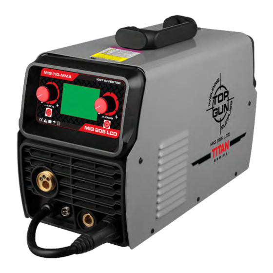
- Page 1 Manual Guide 205 LCD 1PH MIG - STICK - TIG TOPGUNWELDING.COM.AU...
- Page 3 This page has been intentionally left blank.
- Page 4 SAFETY INFORMATION PAGE 1 MACHINE SPECIFICATIONS PAGE 5 WELDING TECHNIQUES PAGE 5-6 INSTALLATION AND OPERATION PAGE 7 WELDING SETTINGS QUICK REFERNCE CHART PAGE 17 JOINT PREPERATION PAGE 18 ACCESSORIES AND CONSUMABLES PAGE 19...
-
Page 5: Safety Info
Safety Info SAFETY INFO AND TIPS WARNING PROTECT YOURSELF AND OTHERS FROM POSSIBLE SERIOUS INJURY OR DEATH .KEEP CHILDREN AWAY. IF WEARING A PACEMAKER KEEP AWAY UNTIL CONSULTING YOUR DOCTOR. DO NOT LOSE THESE INSTRUCTIONS. READ OPERATING/INSTRUCTION MANUAL BEFORE INSTALLING, OPERATING OR SERVICING THIS EQUIPMENT. Welding products and welding processes can cause serious injury or death, damage to other equipment or property, if the operator does not observe all safety rules and take precautionary measures. -
Page 6: Safety Precautions
SAFETY PRECAUTIONS FOLLOW THE BELOW PRECAUTIONS CAREFULLY. IMPROPER USE OF ANY WELDER MAY RESULT IN SERIOUS INJURY OR DEATH. ONLY CONNECT WELDER TO A POWER SOURCE FOR WHICH IT IS DESIGNED. The specification plate on the welder lists this information.When welding outdoors, only use an extension cord which is designed for outdoor use. -
Page 7: Fumes And Gases
FIRE & EXPLOSIONS ARC RAYS The WELDING operation can potentially cause fire or an ARC RAYS can burn eyes and skin; NOISE can damage hearing. explosion as Sparks and spatter are emitted from thewelding ARC RAYS from the welding process produce an intense heat arc. - Page 8 PROLOGUE THANKYOU FOR CHOOSING A TOPGUN WELDING AUSTRALIA PRODUCT PLEASE READ AND UNDERSTAND THIS MANUAL BEFORE OPERATING THE WELDING PLANT. PLEASE ONLY USE AUTHORIZED ACCESSORIES AND CHECK FOR CORRECT FITMENT BEFORE USE. PLEASE DO NOT MODIFY MACHINE IN ANY MANNER AS THIS MAY VOID WARRANTY AND INCREASE CHANCES OF SERIOUS INJURY OR DEATH.
-
Page 9: Specifications
Specifications MACHINE SPECS This information can be found on top of the machine. 200 LCD Input Voltage (V) 240 A/C 200 LCDPFC TGWMIG200LCD Frequency (Hz) 50 Hz Output Current Range (A) 30-180A Rated Duty Cycle (% ) 40% @ 200A Wire Sizes 0.6 -1.2mm 15.5 kg... -
Page 10: Getting Started
Getting Started WELDING 101 Striking An Arc Practice this on a piece of scrap plate before going on to more exacting work.The easiest welding procedure for the beginner to experiment with MIG welding is in the flat position. The equipment is capable of flat, vertical and overhead positions. Two different welding processes are covered in this section (GMAW and FCAW), with the intention of providing the very basic concepts in using the Mig mode of welding, where a welding gun is hand held, and the electrode (welding wire) is fed into a weld puddle, and the arc is shielded by an inert welding grade shielding gas or inert welding grade shielding gas mixture. -
Page 11: Installation
Installation AND OPERATION Make sure that the supply voltage matches the voltage requirements indicated. (15% deviation is allowed) If you increase the length of the leads, be aware that possible damage may occur with excessively long leads. -Ground the unit with a minimum of 6mm²(10 gauge) wire to the earth ground as the drawing. -Connect the earth lead connector to the negative (-) quick-connection terminal, and turn clockwise to tighten. - Page 12 13 13 Wire Tension Adjustment Wire Tension Arm & Support Wire Input Roller Wire Roller Retainer Wire Spool Retainer Spool Brake Adjustment Welding Gas Inlet (P/N: TT300510 ) (P/N: TT150002 ) Torch Trigger Switch Torch “Euro” Connector Workpiece Earth Clamp (P/N: TT100200 ) Earth Lead Quick Connector (P/N: TT200300)
-
Page 13: Operation
Operation MIG Welding Set Up & Operation Fitting the spool open the cover door for the wire feed compartment. Remove the wire spool retainer (18) by threading off anti clockwise. fit the 200mm diameter wire spool to the spool holder, ensuring the end of the wires exits towards the wire feeder from the bottom of the spool. - Page 14 Note - Gas shielded MIG welding requires a shielding gas supply, gas regulator and gas shielded MIG wire. These accessories are not supplied standard with the 205 LCD Connect the MIG Torch Euro Connector (21) to the torch socket on the front of the welder (5). Secure by firmly hand tightening the threaded collar on the MIG Torch Euro Connector clockwise.
- Page 15 Connect Earth Clamp (22) to the work piece. Contact with workpiece must be strong contact with clean, bare metal, with no corrosion, paint or scale at the contact point. Connect the gas regulator (optional) and gas line to the inlet on the rear panel (11). If the regulator is equipped with a flow gauge, the flow should be set between 8 –...
-
Page 16: User Interface
User Interface Controls for MIG welding Switch the machine on using the mains power switch (10). Wait 5 seconds for the digital control program to load up. Press the Left button (2) to mode secretion, and select the mode by Left knob (1), and press the Left knob (1) to confirm the selection. - Page 17 To adjust the voltage independently, Rotate Left Knob (1) to adjust the welding voltage. This will change and give the display screen as below. -5v~+5v Then use the Left knob (1) to adjust the welding voltage -5~+5V from the standard synergic setting. This will not change the wire speed.
- Page 18 The default value of inductance is 10, it is recommended to keep this value unless the operator is an experienced welder. Press the Right Button (4) again to return to the main wire speed/voltage adjustment screen. If the control panel is not adjusted after 5 seconds it will also return to the primary MIG adjustment mode. Or press the Left/Right (1)/(3) to return to the primary MIG adjustment mode directly.
- Page 19 Once the wire comes out past the end of the torch neck, pull the torch trigger or press any button on the display to stop the automatic wire feed. Close the wire feed cover door Replace the welding tip (25) and conical nozzle (24) back onto the torch neck and trim off any excess wire You are now ready to weld! MMA/STICK mode operation Note - MMA/Stick Welding requires an MMA lead set .
- Page 20 Connect Earth Clamp (22) to the work piece. Contact with workpiece must be strong contact with clean, bare metal, with no corrosion, paint or scale at the contact point. Connect the TIG torch power lead to the negative (-) welding output terminal (7). Connect the gas supply to the TIG torch.
-
Page 22: Joint Preparation
Joint Preparation In many cases, It will be possible to weld steel sections without any special preparation. For heavier sections and for repair work on castings, etc, it will be necessary to cut or grind an angle between the pieces being joined to ensure proper penetration of the weld metal and to produce structurally sound joints. -
Page 23: Accessories And Consumables
Accessories and Consumables PARTS AND SPARES HAND PIECE 300 Amp ACCLP300 Earth Clamps 400 Amp ACCLP400 500 Amp ACCLP500 300 Amp MAWEC300 Magnetic Earth Clamps 800 Amp MAWEC800 200 Amp ACEHTL200 Electrode Holders -Twist Lock 300 Amp ACEHTL300 400 Amp ACEHTL400 200 Amp ACEHTT200... - Page 24 HELMETS Model Part No. Gloss Black -TGHWARGBLK Topgun Warrior Series Blue Inferno -TGHWARBLUINF Auto Darkening Welding Helmet Red Inferno -TGHWARINFERNO Carbon Fibre -TGHWARCFIBRE Warrior Helmet Harness TGTHH Warrior Helmet Inner Lens Pk5 TGHLWI Warrior Helmet Outer Lens Pk5 TGHLWO Model Part No.
- Page 25 This page has been intentionally left blank.
Need help?
Do you have a question about the 205 LCD and is the answer not in the manual?
Questions and answers