Table of Contents
Advertisement
Quick Links
Advertisement
Table of Contents

Related Manuals for Top Gun PLASMA CUT 42 PFC


Summary of Contents for Top Gun PLASMA CUT 42 PFC
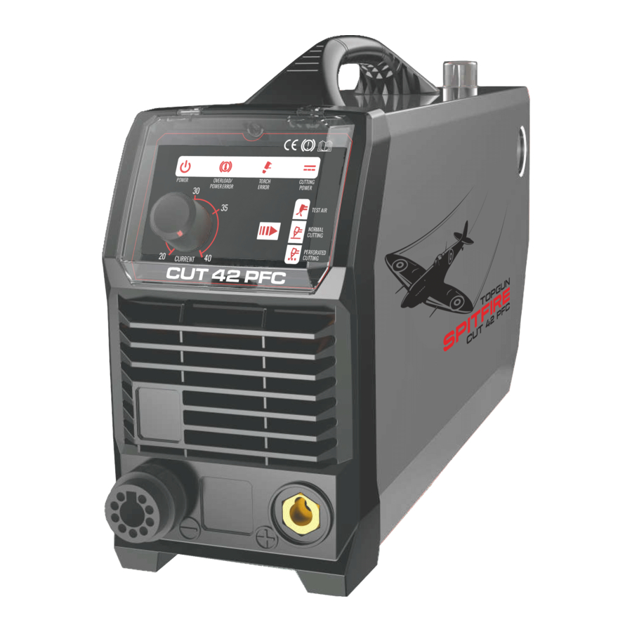
- Page 1 Manual Guide PLASMA CUT 42 PFC 40A PLASMA CUTTER TOPGUNWELDING.COM.AU...
- Page 2 PROLOGUE THANK YOU FOR CHOOSING A TOPGUN WELDING AUSTRALIA PRODUCT PLEASE READ AND UNDERSTAND THIS MANUAL BEFORE OPERATING THE PLASMA UNIT. PLEASE ONLY USE AUTHORIZED ACCESSORIES AND CHECK FOR CORRECT FITMENTS BEFORE USE. PLEASE DO NOT MODIFY MACHINE IN ANY MANNER AS THIS MAY VOID WARRANTY AND INCREASE CHANCES OF SERIOUS INJURY OR DEATH.
- Page 3 PAGE 1 SAFETY INFORMATION OVERVIEW PAGE 4 MACHINE SPECIFICATIONS PAGE 5 FEATURES, CONTROLS AND OPERATION PAGE 6 FIXES AND FAULTS PAGE 12 ACCESSORIES AND CONSUMABLES PAGE 16...
-
Page 4: Safety Info
Safety Info SAFETY INFO AND TIPS OPERATION AND MAINTENANCE OF PLASMA ARC EQUIPMENT CAN BE DANGEROUS TO YOUR HEALTH • Plasma arc cutting produces intense electric and magnetic emissions that may interfere with the proper function of cardiac pacemakers, hearing aids, or other electronic health equipment. Persons who work near plasma arc cutting applications should consult their medical health qualified technician and the manufacturer of the health equipment to determine whether a hazard exists. - Page 5 FIRE AND EXPLOSION • Fire and explosion can be caused by hot slag, sparks, or the plasma arc. • Be sure there is no combustible or flammable materials in the workplace. Any material that cannot be removed must be protected. •...
- Page 6 OVERVIEW FEATURES • IGBT inverter technology for smooth, stable output and • Increased reliability . • Active PFC technology for increased duty cycle and efficiency. • Multi-voltage input means the unit can even be used with long extension leads reliably. •...
-
Page 7: Specifications
SPECIFICATIONS MACHINE SPECS PLASMA CUT 42 PFC Input Voltage (V) 240 A/C Rated Input Current (A) 23 A Rated Input Power (KW) Output Current Range (A) 20 - 40 A Max No-Load Voltage (V) Rated Duty Cycle (%) 35% @ 40A... - Page 8 WORKING PRINCIPLE The working principle of The TOPGUN CUT series of Air Plasma Cutting machines is shown in the below diagram. Single-phase 110V/220V line frequency (50/60 Hz) AC is rectified into DC, then it is converted to medium frequency AC by inverter device (discrete IGBT), after reducing voltage by medium transformer (the main transformer) and rectified by medium frequency rectifier (fast recovery diode), and is outputted by inductance filtering.
- Page 9 INSTALLATION & OPERATION Layout for the front and rear panel Plasma Torch Euro/ Central Connector. Earth Lead Connection Socket. Grid Cutting.(Mesh etc) Normal Cutting Gas Function Test Cutting Power Indicator: Lights when cutting power circuit activated. Torch System Error Indicator. Alarm Indicator.
-
Page 10: Electrical Connection
Pilot Arc System The TOPGUN CUT series of Air Plasma Cutting machines use a pilot arc system to establish the main cutting arc. A pilot arc system is a circuit where the return is back through the torch head and cable. This means it can create a small arc with low cutting power without making any electrical connection with the main machine earth. -
Page 11: Cutting Operation
Basic Operation Connect the earth cable quick connector to the earth connection socket (2) Connect the earth clamp to the work piece. Contact with the workpiece must be firm and contact with clean, bare metal, with no corrosion, paint or scale at the contact point. Connect the plasma torch to the machine central connector (1) ensuring the collar is done up firmly by hand. - Page 12 PLASMA CUTTING GUIDE Cutting Guide Effect of Cutting Speed Piercing Technique NOTE: Keep moving while cutting. Cut at a steady speed without pausing. Maintain a constant cutting speed so that the arc lag is 10° to 20°behind the travel direction. Use a 5°- 15° leading angle in the direction of the cut. OPERATING TECHNIQUES 1.
- Page 13 Note: The speeds given here are typical for best quality cuts. Your actual speeds may vary depending on material composition, surface condition, operator technique, etc. If the cutting speed is too fast, you may lose the cut. With slower speeds excessive dross may accumulate. If speed is too slow, the arc may extinguish.
-
Page 14: Troubleshooting
Fixes and Faults TROUBLESHOOTING Trouble Possible Reason Suggested Remedy Torch will not activate 1.Power switch OFF 1.Turn power switch to the ON position 2.Air supply is not of sufficient 2. Check air supply(60–80 PSI, 3.5cfm volume or pressure required) 3. Work piece ground clamp not 3. - Page 15 OPERATING ENVIRONMENT • Height above sea level ≤1000 M • Operation temperature range -10 ~ +40°C • Air relative humidity is below 90% ( 20°C) • Preferably sit the machine some angles above the floor level, and ensure the maximum angle does not exceed 15°C. •...
-
Page 16: Maintenance
Maintenance AND TROUBLESHOOTING CUTTING GUN MAINTENANCE Warning : 1. Check the consumable parts for damage, if worn, replace them (use only genuine TOPGUN parts). 2. Turn off the power source before checking or removing torch parts. Note: When operating the torch under normal conditions, a small amount of gas vents through the gap between the shield cup and the torch handle, Do not attempt to over tighten the shield cup as irreparable damage to internal components may result. -
Page 17: Difficult Starting
TROUBLESHOOTING WARNING A. Power lamp and temperature lamp on. Air flow blocked, check for blocked air flow on the unit and correct. Fan blocked, check and correct. Unit is overheated, let the unit cool down for at least 5 minutes. Make sure the unit has not been operated beyond Duty Cycle limit, refer to technology parameters in Section 2. -
Page 18: Accessories And Consumables
Accessories and Consumables PARTS AND SPARES CONSUMABLES Spare Parts Part Number Description 1 ES96506 Electrode 5PC L/Life 2 TGPC60028 Swirl Ring 3A TGPCPD011608 Cutting Tip 0.8mm 3B TGPCPD010210 Cutting Tip 1.0mm 4 TGPC60389 Retaining Cap 5 TGPCHR60D Spacer Crown Circle Cutting Guide to suit PT60 TGWP41KIT... - Page 19 HELMETS Model Part No. Gloss Black - TGHWARGBLK Topgun Warrior Series Blue Inferno - TGHWARBLUINF Auto Darkening Welding Helmet Red Inferno - TGHWARINFERNO Carbon Fibre - TGHWARCFIBRE Warrior Helmet Harness TGTHH Warrior Helmet Inner Lens Pk5 TGHLWI Warrior Helmet Outer Lens Pk5 TGHLWO Model Part No.
- Page 20 ELECTRICAL SCHEMATIC DRAWING...
- Page 21 This page has been intentionally left blank.
Need help?
Do you have a question about the PLASMA CUT 42 PFC and is the answer not in the manual?
Questions and answers