Table of Contents
Advertisement
Advertisement
Table of Contents

Related Manuals for Top Gun MIG-210L


Summary of Contents for Top Gun MIG-210L
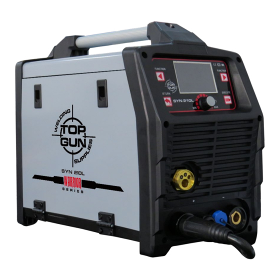
- Page 1 USER MANUAL MIG-210L FULL-COLOR LCD GAS SHIELDED WELDER...
-
Page 2: Table Of Contents
Contents SAFETY......................1 CAUTION ......................3 MIG-200GD TECHNICAL DATA ................5 MIG INSTALLATION ..................6 LIFT TIG INSTALLATION..................8 MMA INSTALLATION ..................9 OPERATION PANEL INSTRUCTION ..............10 MEMORY FUNCTION ..................16 LIFT TIG SETTING GUIDE ................. 18 MMA SETTING GUIDE..................20 TROUBLE SHOOTING .................. -
Page 3: Safety
Machine Operating Safety • Do not switch the function modes while the machine is operating. Switching of the function modes during welding can damage the machine. Damage caused in this manner will not be covered under warranty. • Disconnect the electrode-holder cable from the machine before switching on the machine, to avoid arcing should the electrode be in contact with the work piece. - Page 4 hazardous to your health. Do not breathe the smoke and gas generated whilst welding or cutting, keep your head out of the fumes • Keep the working area well ventilated, use fume extraction or ventilation to remove welding/cutting fumes and gases. •...
-
Page 5: Caution
• Have a fire extinguisher nearby and know how to use it. Be alert that welding/cutting sparks and hot materials from welding/cutting can easily go through small cracks and openings to adjacent areas. Be aware that welding/cutting on a ceiling, floor, bulkhead, or partition can cause fire on the hidden side. - Page 6 i. The environment in which this welding/cutting equipment is installed must be free of grinding dust, corrosive chemicals, flammable gas or materials etc, and at no more than maximum of 80% humidity. ii. When using the machine outdoors protect the machine from direct sun light, rain water and snow etc; the temperature of working environment should be maintained within -10°C to +40°C.
- Page 7 possibly occur. ATTENTION! - CHECK FOR GAS LEAKAGE At initial set up and at regular intervals we recommend to check for gas leakage Recommended procedure is as follows: 1. Connect the regulator and gas hose assembly and tighten all connectors and clamps. 2.
- Page 8 MIG-210L TECHNICAL DATA Gas Metal Arc Welding (GMAW) is an arc welding process where a consumable wire is fed by motor driven feed rolls to a welding gun, and where welding current is supplied from the welding power source. The welding arc is struck between the work piece and the end of the wire, which melts into the weld pool.
- Page 9 Size (mm) 460x220x375mm Weight (kg) 15.6kg...
-
Page 10: Mig Installation
OPERATION MANUAL MIG INSTALLATION For solid wire welding For Flux-cored wire welding 1.Connect the welding torch into the Euro Mig torch connection socket on the front panel, and tighten it. 2.Insert the earth cable plug into the required polarity and tighten -negative for gas shielded wires positive for gas less wires. - Page 11 6.At the wirefeed assembly, release the compression screw by swivelling it outwards. This allows the top roller arm to spring to the open position.The end of the welding wire can now be passed through the inlet guide, over the bottom driven roller, and into the output wire guide tube.
- Page 12 Accessories: V GROOVE DRIVE ROLLER - STEEL WIRE 1 x 0.8-0.9 V KNURLED GROOVE DRIVE ROLLER – FLUX CORED WIRE 1 x 0.9-1.2 K...
-
Page 13: Lift Tig Installation
MIG-210L LIFT TIG INSTALLATION In the TIG (Tungsten Inert Gas) method, the electric arc strikes under an inert gas (argon) shield, between the welded element and the non-fusible electrode made of pure tungsten or tungsten with additives. The TIG method is especially recommended for aesthetic and high-quality joining of metals, without laborious mechanical treatment after welding. - Page 14 1.Connect the welding torch into the Euro Mig torch connection socket on the front panel, and tighten it. 2.Insert the earth cable plug into the positive socket. The TIG torch plug into negative socket. 3.Connect Gas Line from the torch to Gas Regulator and connect the gas regulator to the Gas Cylinder. Carefully open the valve of the gas cylinder, set the flow to 5 l/min.
-
Page 15: Mma Installation
MIG-210L MMA INSTALLATION Arc welding is also called the MMA (Manual Arc Welding) method and is the oldest and most versatile arc welding method. The MMA method uses a coated electrode, consisting of a metal core covered with a lagging. An electric arc is created between the end of the electrode and the material being welded. - Page 16 Connect the welding and mass leads to the appropriate output connectors of the welder, according to the polarity recommended by the manufacturer of the electrodes you intend to weld.
-
Page 17: Operation Panel Instruction
MIG-210L OPERATION PANEL INSTRUCTION Function switch button to the left menu. Press over 5 seconds switch to data call page. Function selection: When you choose a function, the relative icon will be highlighted. Return button,switch to the parent menu,or return. Press over 5 seconds will back to factory... - Page 18 Data adjusting knob. According left or right button, to switch the relative menu, and turn this knob can adjust the data. Quick turning:Press down and turn the knob at the same time for larger adjusting, faster.Fine turning: Just to adjust the knob for precise adjusting, slower. Execute button, press it can enter into sub-menu, or execute the current operation.
- Page 19 Press button to select the welding mode you want to do, then press to next step. 3.AUTO MODE Under the Auto mode, you can select the material, thickness and the wire diameter, then you can start your welding, the machine will recommend the welding current, voltage and the wire feeding speed for you. Of cause you can adjust them yourself according the welding needs.
- Page 20 2.Select of plate thickness Spin the knob to adjust plate thickness. 3.Selection of wire diameter Select the corresponding wire diameter. The device will recommend the right voltage and current for you. 4.MIG MODE SETTING Selection of handle methods 2-step welding: When you press the torch, it start to weld by holding the button, when release, it stop welding.
- Page 21 Selection of welding pulse Please notice that pulse function only execute in synergy mode. 1 no pulse: when both lights off, the device is in no pulse mode. 2 Single pulse: when single pulse lights illuminates. (See chapter WELDING MIG / MAG WITH PULSE) 3 Dual pulse:when dual pulse lights...
- Page 22 Selection of wire feeding speed Adjust the wire feeding data, until the left-top data can match the real thickness of the work. Selection of Voltage At the beginning, please adjust the data to “0”, and try welding. If the arc too short, please adjust it higher, otherwise, adjust it lower.
- Page 23 Select the “Peak feeding” function adjust the data until the left-top data match the real thickness of the work piece. Selection of dual pulse frequency Recommended adjusting range is 1-2Hz according your welding swing. Selection of dual pulse duty cycle It’s recommended to be used in range of 30%-40%.
-
Page 24: Memory Function
Selection of Base feeding function Adjust the data. It’s recommended to adjust within 70%-90% of the peak feeding. MEMORY FUNCTION MIG-2 possess 18 sets memories. Long press 3 seconds to restore current setting. Long press 3 seconds to recall setting. - Page 25 MIG-210L MIG Welding Current-Wire Diameter And Plate Thickness Chart Wire diameter Plate thickness Wire speed ( M/min ) AL-Si1.0/(4043) (DCEP) Welding current (A) Arc voltage 16.0 18.3 19.2 21.0 22.5 Wire speed ( M/min ) AL-Si1.2/(4043) (DCEP) Welding current (A) 27.0...
- Page 26 Arc voltage 19.7 23.5 25.6 28.5 29.6 Instruction : Al and Al-Si wire both use Al-Si Function.
-
Page 27: Lift Tig Setting Guide
OPERATION MANUAL LIFT TIG SETTING GUIDE In the TIG (Tungsten Inert Gas) method, the electric arc strikes under an inert gas (argon) shield, between the welded element and the non-fusible electrode made of pure tungsten or tungsten with additives. The TIG method is especially recommended for aesthetic and high-quality joining of metals, without laborious mechanical treatment after welding. - Page 28 MIG-210L WELDING POLARITY IN THE TIG METHOD Negative polarity is used for most TIG welding operations. The welding gun is connected to the negative pole, while the earth gun is connected to the positive pole. In this way, the electrode consumption is reduced, the amount of heat accumulated in the welded material increases.
- Page 29 18ga(1.024mm) 17ga(1.5mm) 14ga(2.0mm) 1/8"ga (3.0mm) 5/36"ga (4.0mm) 5/36"ga ≥(4.0mm) 100-150 100-150 ATTENTION! The TIG torch is not standard equipment of the set.
-
Page 30: Mma Setting Guide
OPERATION MANUAL MMA SETTING GUIDE Arc welding is also called the MMA (Manual Arc Welding) method and is the oldest and most versatile arc welding method. The MMA method uses a coated electrode, consisting of a metal core covered with a lagging. An electric arc is created between the end of the electrode and the material being welded. - Page 31 Selection of welding current Press welding current, the machine will fit the thickness automatically. VRD function Press the button to activate VRD function. When the green light illuminate. It means the VRD function is activated. Press the button again to turn off. We recommend user turn on VRD when using MMA welding.
- Page 32 Force current Stabilizes the arc regardless of fluctuations in its length, reduces the amount of spatter. MMA WELDING ELECTRODE DIAMETER PLATE THICKNESS AND CURRENT DIAMETER 2.5mm 3.2mm Eelectrode Diameter/ Plate Thicnkness Amps. Amps. Amps. 17ga(1.5mm) 14ga(2.0mm) 1/8"ga (3.0mm) 5/36"ga (4.0mm) 1/16"(5.0mm) 1/4"(6.0mm)
-
Page 33: Trouble Shooting
MIG-210L TROUBLE SHOOTING Malfunctions Solution Confirm the power switch is on. The meter show nothing; Power supply available for input cable. Check if the three phase commute bridge is damaged. Fan does not rotate; There is malfunction occurs in the supplementary power source on ... - Page 34 The vh-07 plug-in voltage of multimeter to MOS panel should be about DC308V When the fan turns, the abnormal The auxiliary power on MOS panel has a green indicator light. If the light is indicator light is not on and there is no not on, the auxiliary power is not working high frequency discharge sound, and no gas flow from the cutting torch...
-
Page 35: Maintenance
Avoid situations where water or steam can enter the device. If the welder gets wet, dry it and then check the insulation of the device (also between joints and contacts). After checking that everything is OK, you can continue working. SET CONTAINS: - MIG-210L welder main body - Ground clamp with 2m cable - 35 mm EURO fast plug - AC36V heating gas regulator - 0.8-1.0V 1.0-1.2U wire roller... -
Page 36: Circuit
MIG-210L CIRCUIT... - Page 37 OPERATION MANUAL...
- Page 38 OPERATION MANUAL...
Need help?
Do you have a question about the MIG-210L and is the answer not in the manual?
Questions and answers