Table of Contents
Advertisement
Quick Links
Advertisement
Table of Contents

Related Manuals for Top Gun TGWMIG2500LSWF


Summary of Contents for Top Gun TGWMIG2500LSWF
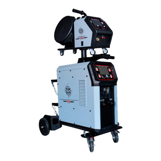
- Page 1 USER MANUAL TGWMIG2500LSWF...
-
Page 3: Table Of Contents
Please read carefully this user manual before using this machine Keep it for the future use. MANU SAFETY APPLICATION DESCRIPTION OF THE MACHINE TECHNICAL DATA OF THE DEVICE DEVICE CONNECTION - WELDING POLARITY SETTING PANEL OPERATION-GENERAL -SYNERGY MODE FOR MAG/MIG -MIG OPERATION -TIG OPERATION -MMA OPERATION... -
Page 4: Safety
Safety It is imperative that you read the following signs and safety rules to protect your own and other people's health and life. Read the instructions before starting the device. Use only original equipment supplied by the manufacturer. Some components may explode. Always use a face shield and protective clothing with long sleeves. - Page 5 USER MANUAL Make sure that cylinders are handled and stored in accordance with health and safety and fire protection requirements. Welded parts may burn. The protruding wire from the torch is sharp and can cause skin puncture. Danger of fire and explosion. During welding work, a fire may result. The welding station must be remote and protected against flammable and explosive materials.
- Page 6 USER MANUAL ATTENTION! The heating test was carried out at ambient temperature and the duty cycle (load factor) at 25℃ was determined as a result of the simulation. The device is intended for conducting professional welding works in industrial conditions by personnel having valid qualification certificates in accordance with applicable standards.
-
Page 7: Application
USER MANUAL 2. APPLICATION The devices are used for manual arc welding in the GMAW (Gas Metal Arc Welding), GTAW (Gas Tungsten Arc Welding) and SMAW (Shielded Metal Arc Welding) methods. 3. DESCRIPTION OF THE MACHINE The devices are modern inverter sources offering very high welding versatility. Their main advantage is the possibility of welding using single or double pulse current in MIG or MAG mode. -
Page 8: Device Connection - Welding Polarity Setting
USER MANUAL 5. DEVICE CONNECTION - WELDING POLARITY SETTING MIG/MAG WELDING Select the correct welding polarity as shown above. Positive polarity welding (MIG / MAG gas shielded solid wire welding) Welder's current plug connected to the positive + socket (EURO) Earth handle connected to the negative socket - WARNING! To start working with self-shielding wire, change the polarity inside the device - on the wire feeder. - Page 9 USER MANUAL Ensure that the power supply network can provide coverage of the input power demand for this device under normal operating conditions. The fuse size, the parameters of the power cord are given in the technical data and on the rating plate. Connection and replacement of the power cord and plug should be made by a qualified electrician.
- Page 10 USER MANUAL Insert the end of the wire into the guide located at the back of the feeder and route it over the drive roller by inserting it into the welding gun stub. Tighten the wire in the drive roller groove and tighten. ...
- Page 11 USER MANUAL consumable electrode and the material being welded ensures the formation of the weld under very favorable thermal and chemical conditions. This type of welding can be used to make high- quality joints of all metals that can be joined by arc welding. These include: carbon and low alloy steels as well as corrosion resistant steels.
-
Page 12: Panel Operation-General
USER MANUAL 7. PANEL OPERATION A. DESCRIPTION OF THE CONTROL PANEL 1. LCD display 2. Function selection button, to select the previous menu, holding for 5 seconds to save the current setting in memory. 3. Button to return to the previous menu. (additionally held for 5 seconds to return to the factory settings (RESET)). - Page 13 USER MANUAL 1. Back button. Press the go back to last page 2. Enter button. Press to go to next page. 3. Voltage adjust knob. Spin to adjust voltage parameter 4. Parameter adjust knob. Spin to adjust parameter according to the LCD panel. Press to confirm and go to next selection.
- Page 14 USER MANUAL B. CHOICE OF WELDING METHOD This page allows you to select welding methods as below: Synergy, MIG, LIFT-TIG, MMA Turn the red knob of the font panel to select the welding mode then press for confirmation. SYNERGY - synergic settings. The user selects the basic welding parameters such as the type of material, thickness of the material to be welded, diameter of the welding wire.
-
Page 15: Synergy Mode For Mag/Mig
USER MANUAL VRD - the device has a VRD (Voltage Reduction Device) system, which for welding mode MMA with electrodes reduces the open circuit voltage, which significantly increases the user's safety. In special cases of using electrodes with high arc ignition current, problems with its initiation may occur. C. - Page 16 USER MANUAL Step 3 Selecting the welding wire diameter You choose the welding wire diameter you plan to use. ATTENTION! The device automatically reduces or increases its maximum power depending on the wire diameter. Step 4 Selecting the welding wire diameter You choose the welding wire diameter you plan to use.
-
Page 17: Mig Operation
USER MANUAL D. MIG/MAG OPERATION In MIG welding mode, the user sets all welding parameters one after the other. The system suggests the selection of optimal welding parameters by indicating at their adjustment thickness of the welded material (see table - setting the wire feeder speed). This information suggests to the user that the settings are correct. - Page 18 USER MANUAL Choice of welded material (and wire) From the list of alloys available in program. Setting the wire feeder speed ATTENTION! It will show automatically the estimated thickness of the welded material in order to select the optimal welding parameter. Adjusting the arc voltage Increasing or decreasing this value will lengthen or shorten the arc length.
- Page 19 USER MANUAL Adjusting the arc voltage Increasing or decreasing this value will lengthen or shorten the arc length. Inductance regulation Properly selected welding inductance reduces the amount of spatter. It depends on the wire diameter welding, shielding gas used, current and welding position.
- Page 20 USER MANUAL E. MIG / MAG WELDING WITH PULSE In order to start welding in MIG / MAG PULS mode, the settings should be made as in the previous chapter. Additional welding parameters in pulse welding mode are presented in the following tables: Welding current selection2 The pulse current function is mainly used when...
- Page 21 USER MANUAL F. MIG / MAG WELDING WITH DOUBLE PULSE To start welding in MIG / MAG mode, double PULSES should be pre-set as in the BASIC MIG / MAG SETTINGS chapter. Additional welding parameters in mode double pulse current welding is shown in the table below: Welding current selection 3 - double pulse Choose double pulse when welding aluminum.
- Page 22 USER MANUAL Setting the minimum wire feeder speed ATTENTION! When adjusting this parameter, you can refer to the dynamic thickness data that shown on the left, until the data match with the real thickness of the workpiece. or change a little bit as you need.
- Page 23 USER MANUAL I. MIG Setting Chart MIG Welding Current-Wire Diameter And Plate Thickness Chart Wire diameter Plate thickness 10.0 Wire speed(M/min) AL-Si1.0/(4043) Welding current (A) (DCEP) Arc voltage 16.0 18.3 19.2 21.0 22.5 23.6 Wire speed(M/min) AL-Si1.2/(4043) Welding current (A) 27.0 (DCEP) Arc voltage...
-
Page 24: Tig Operation
TIG Welding In the TIG (Tungsten Inert Gas) method, the electric arc strikes under an inert gas (argon) shield, between the welded element and the non-fusible electrode made of pure tungsten or tungsten with additives. The TIG method is especially recommended for aesthetic and high-quality joining of metals, without laborious mechanical treatment after welding. - Page 25 USER MANUAL WELDING POLARITY IN THE TIG METHOD Negative polarity is used for most TIG welding operations. The welding gun is connected to the negative pole, while the earth gun is connected to the positive pole. In this way, the electrode consumption is reduced, the amount of heat accumulated in the welded material increases.
-
Page 26: Mma Operation
USER MANUAL MMA WELDING Arc welding is also called the MMA (Manual Arc Welding) method and is the oldest and most versatile arc welding method. The MMA method uses a coated electrode, consisting of a metal core covered with a lagging. An electric arc is created between the end of the electrode and the material being welded. - Page 27 USER MANUAL Welding current setting Adjust the welding current by spin the knob. HOT-START A function that makes welding easier. When the arc strikes, the welding current is temporarily increased to heat up the material and electrode at the point of contact, and to properly shape the penetration and weld face at the initial stage of welding.
-
Page 28: Error Code
USER MANUAL 8. ERROR CODE In special cases, the following messages may appear on the display indicating a problem with the operation of the device. Errors on the display will appear until the defect is removed. Error 001 Over current The device is operated beyond its rated efficiency. -
Page 29: Eletricity Safety Guidlines
USER MANUAL 9. ELECTRICITY SAFETY GUIDELINES WORKING CONDITIONS Optimal ambient temperature between -10 ° C and 40 ° C. Avoid welding in sunny conditions and when it is raining, do not allow water to get inside the device. Avoid working in flammable, aggressive or dust environments. WORK SAFETY Properly installed device with over voltage, over current protection and protection against excessive temperature will automatically turn off under conditions beyond those specified as standard. -
Page 30: Electricity Diagram
USER MANUAL 10 . ELECTRICAL DIAGRAM...
Need help?
Do you have a question about the TGWMIG2500LSWF and is the answer not in the manual?
Questions and answers