Advertisement
Quick Links
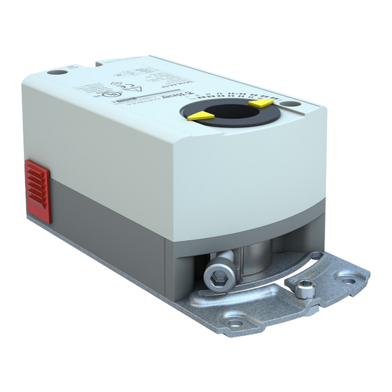
DC(M)24-44-88 Series
DC(M)24-44-88 Series - Installation, Operation and Maintenance Manual
Technical Specifications . . . . . . . . . . . . . . . . . . . . . . . . . . . . . . . . . . . . . . . . . . . . . . . . . . . . 2,3
Safety Instructions/Description . . . . . . . . . . . . . . . . . . . . . . . . . . . . . . . . . . . . . . . . . . . . . . . 4
Installation . . . . . . . . . . . . . . . . . . . . . . . . . . . . . . . . . . . . . . . . . . . . . . . . . . . . . . . . . . . . . . . .5-7
Wiring. . . . . . . . . . . . . . . . . . . . . . . . . . . . . . . . . . . . . . . . . . . . . . . . . . . . . . . . . . . . . . . . . . .8-10
Dimensions . . . . . . . . . . . . . . . . . . . . . . . . . . . . . . . . . . . . . . . . . . . . . . . . . . . . . . . . . . . . . . . 10
PLEASE VISIT OUR WEBSITE –
— 44-88 lb-in (5 Nm-10 Nm) Electric Actuator
IOM Manual
Table of Contents
FOR MORE INFORMATION ON THIS PRODUCT
AND OTHER BRAY PRODUCTS
www.braycommercialdivision.com
1
Bray Commercial Division
13788 West Road, Suite 200A
Houston, Texas 77041
BCDSales@Bray.com
Phone: 1-888-412-2729
www.braycommercialdivision.com
© 2022 Bray International, Inc.
09/11/24
Advertisement

Related Manuals for Bray DC24 Series


Summary of Contents for Bray DC24 Series
- Page 1 Bray Commercial Division 13788 West Road, Suite 200A Houston, Texas 77041 BCDSales@Bray.com Phone: 1-888-412-2729 www.braycommercialdivision.com © 2022 Bray International, Inc. 09/11/24 DC(M)24-44-88 Series — 44-88 lb-in (5 Nm-10 Nm) Electric Actuator IOM Manual Table of Contents DC(M)24-44-88 Series - Installation, Operation and Maintenance Manual Technical Specifications .
- Page 2 Disclaimer - The performance specifications are nominal and conform to acceptable industry standards. For application at conditions beyond these specifications, consult the nearest Bray office. Bray controls shall not be liable for damages resulting from misapplication or misuse of its products.
- Page 3 Disclaimer - The performance specifications are nominal and conform to acceptable industry standards. For application at conditions beyond these specifications, consult the nearest Bray office. Bray controls shall not be liable for damages resulting from misapplication or misuse of its products.
- Page 4 DC(M)24-(44/88) Series Installation, Operation & Maintenance Manual Continued Safety Instructions - Definition of Terms Read, Follow and Save these instructions WARNING Personal injury/loss of life may occur if you do not follow a procedure as specified. CAUTION Equipment damage or loss of data may occur if you do not follow a procedure as specified. NOTICE Used without the safety alert symbol indicates a potential situation which, if not avoided, may result in an undesirable result or state, including property damage.
- Page 5 DC(M)24-(44/88) Series Installation, Operation & Maintenance Manual Continued When using a 3/8-inch shaft: Remove factory-installed When using a 5/8-inch shaft: 1/2-inch guide. See Figure 3 Figure 3. Removing 1/2-inch Ø Shaft Guide for 3/8-in or 5/8-in Shaft. Figure 5. 5/8-inch Ø Shaft. Remove factory-installed 1/2-inch guide.
- Page 6 DC(M)24-(44/88) Series Installation, Operation & Maintenance Manual Continued Dual Auxiliary Switch Setting For DC24-44-TAP, DCM24-44-AP, DC24-88-TAP, DCM24-88-AP. Factory setting: A = 5° B = 85° Use a flat-blade screwdriver to adjust the A switch. The long arm of the † points to the setting. Manually turn the red ring of the B switch.
- Page 7 DC(M)24-(44/88) Series Installation, Operation & Maintenance Manual Continued Changing Rotation Direction Mechanical Range Limitation and DIP Switch Settings Self–adapt Feature To use the entire 0(2) to 10V input signal to con trol the adjusted range, raise the tab located on the lower left-hand side of the actuator and locate the DIP switches.
- Page 8 DC(M)24-(44/88) Series Installation, Operation & Maintenance Manual Continued Wiring WARNING All wiring must conform to NEC and local codes and Installations requiring Conformance regulations. • All wiring for CE rated actuators must only be separated Use earth ground isolating step-down Class 2 transformers. extra low voltage (SELV) or protective extra low voltage Do not use autotransformers.
- Page 9 To avoid excessive wear or drive time on the motor, use a controller and/or software that provides a time-out function to remove the signal at the end of rotation (stall). Disclaimer - The performance specifications are nominal and conform to acceptable industry standards. For application at conditions beyond these specifications, consult the nearest Bray office.
- Page 10 DC(M)24-(44/88) Series Installation, Operation & Maintenance Manual Continued Retrofit Wiring Bray Siemens Belimo Honeywell Johnson Modulating Control DCM-44 Series GDE Series LMB Series MN7505 Series M9104 Series (0-10V) DCM-88 Series GLB Series NMB Series MN7510 Series M9109 Series Function Color...
Need help?
Do you have a question about the DC24 Series and is the answer not in the manual?
Questions and answers