Advertisement
Quick Links
Advertisement

Related Manuals for Metrohm 850 Professional IC Anion MSM-HC-MCS


Summary of Contents for Metrohm 850 Professional IC Anion MSM-HC-MCS
- Page 1 850 Professional IC Anion MSM-HC – MCS – 2.850.2070 Manual 8.850.8015EN...
- Page 3 Metrohm AG CH-9101 Herisau Switzerland Phone +41 71 353 85 85 Fax +41 71 353 89 01 info@metrohm.com www.metrohm.com 850 Professional IC Anion MSM-HC – MCS – 2.850.2070 Manual 8.850.8015EN 05.2009 zst...
- Page 4 Teachware Metrohm AG CH-9101 Herisau teachware@metrohm.com This documentation is protected by copyright. All rights reserved. Although all the information given in this documentation has been checked with great care, errors cannot be entirely excluded. Should you notice any mistakes please send us your comments using the address given above.
- Page 5 ■■■■■■■■■■■■■■■■■■■■■■ Table of contents Table of contents 1 Introduction Instrument description ............1 Intended use ................. 3 About the documentation ........... 3 1.3.1 Symbols and conventions ............3 Safety instructions ..............4 1.4.1 General notes on safety ............4 1.4.2 Electrical safety ................
- Page 6 3.14.2 Mode of operation of the injection valve ....... 46 3.14.3 Selecting the sample loop ............47 3.15 Column thermostat ............48 3.16 High Capacity Metrohm Suppressor Module (MSM-HC) ................51 3.16.1 General information on the MSM-HC ........51 3.16.2 Connecting the MSM-HC ............
- Page 7 4.15.2 Protection ................102 4.15.3 Storage ................102 4.15.4 Regeneration ............... 102 4.16 Quality Management and validation with Metrohm ..103 5 Troubleshooting Problems and their solutions .......... 104 6 Technical specifications Reference conditions ............109 Instrument ................. 109 Leak sensor ............... 109 Ambient conditions ............
- Page 8 Table of contents High pressure pump ............110 Sample degasser ............... 111 Injection valve ..............111 6.10 Column thermostat ............112 6.11 High Capacity Metrohm Suppressor Module (MSM-HC) ................112 6.12 Peristaltic pump ..............112 6.13 Metrohm CO suppressor (MCS) ........113 6.14 Conductivity measuring system ........
- Page 9 ■■■■■■■■■■■■■■■■■■■■■■ Table of figures Table of figures Figure 1 Front 850 Professional IC – Anion MSM-HC – MCS ......7 Figure 2 Rear 850 Professional IC Anion MSM-HC – MCS ........ 9 Figure 3 Installation diagram 850 Professional IC – Anion MSM-HC – MCS . . . 16 Figure 4 Connection of capillaries with pressure screws ........
- Page 10 ■■■■■■■■■■■■■■■■■■■■■■ Table of figures Figure 46 Changing the filter ................87 Figure 47 MSM-HC – Components ..............94 Figure 48 Pump tubing connection – Changing the filter ......... 99 ■■■■■■■■ VIII 850 Professional IC – Anion MSM-HC – MCS...
- Page 11 The instrument 850 Professional IC – Anion MSM-HC – MCS (2.850.2070) is one of the model versions of the Professional IC line of instruments manufactured by the Metrohm Company. The Professional IC line of instruments is distinguished by: the intelligence of its components, which are able to monitor and ■...
- Page 12 It provides space for 2 separation columns. High Capacity Metrohm Suppressor Module (MSM-HC) The MSM-HC is used for chemical suppression with high capacity during anion analysis. It is pressure-stable, robust and resistant to solvents.
- Page 13 ■■■■■■■■■■■■■■■■■■■■■■ 1 Introduction interactions with the column. The Metrohm analytical columns are equip- ped with a chip on which their technical specifications and their history (first use / setting up, operating hours, injections, ... ) are saved. Intended use The instrument 850 Professional IC – Anion MSM-HC – MCS is used...
- Page 14 ■■■■■■■■■■■■■■■■■■■■■■ 1.4 Safety instructions Instruction step Carry out these steps in the sequence shown. Warning This symbol draws attention to a possible life hazard or risk of injury. Warning This symbol draws attention to a possible hazard due to electrical current. Warning This symbol draws attention to a possible hazard due to heat or hot instrument parts.
- Page 15 ■■■■■■■■■■■■■■■■■■■■■■ 1 Introduction Warning Only personnel qualified by Metrohm are authorized to carry out service work on electronic components. Warning Never open the housing of the instrument. The instrument could be damaged by this. There is also a risk of serious injury if live components are touched.
- Page 16 ■■■■■■■■■■■■■■■■■■■■■■ 1.4 Safety instructions 1.4.3 Tubing and capillary connections Caution Leaks in tubing and capillary connections are a safety risk. Tighten all connections well by hand. Avoid applying excessive force to tubing connections. Damaged tubing ends lead to leakage. Appropriate tools can be used to loosen connections.
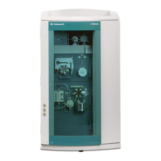
- Page 17 ■■■■■■■■■■■■■■■■■■■■■■ 2 Overview of the instrument 2 Overview of the instrument Front Figure 1 Front 850 Professional IC – Anion MSM-HC – MCS Eluent degasser High pressure pump See Chapter 3.9. See Chapter 3.10. ■■■■■■■■ 850 Professional IC – Anion MSM-HC – MCS...
- Page 18 ■■■■■■■■■■■■■■■■■■■■■■ 2.1 Front Purge valve Pulsation damper For deaerating the high pressure pump (see See Chapter 3.12. Chapter 3.10.1, page 36). Injection valve Sample degasser See Chapter 3.14. See Chapter 3.13. Use optional. Column thermostat Column holder See Chapter 3.15. For two separation columns (see Chapter 3.22, page 68) in the column thermostat and one outside the column thermostat.
- Page 19 ■■■■■■■■■■■■■■■■■■■■■■ 2 Overview of the instrument Rear Figure 2 Rear 850 Professional IC Anion MSM-HC – MCS Knurled screws Vacuum connection For connecting further degassing chambers For fastening the rear panel (2- ) and han- in extension modules. dle (5- Labeled with Vacuum.
- Page 20 2 MSB connectors (labeled with MSB 1 and USB 2). MSB 2) for connecting MSB devices Caution: The 850 must be switched off when connecting a device. MSB = Metrohm Serial Bus. Detector connectors Leak sensor connection socket 2 detector connectors (labeled with Detec- For connecting the...
- Page 21 ■■■■■■■■■■■■■■■■■■■■■■ 2 Overview of the instrument Caution When connecting an instrument to the MSB connector (2-6) you must switch off the 850 Professional IC. ■■■■■■■■ 850 Professional IC – Anion MSM-HC – MCS...
- Page 22 ■■■■■■■■■■■■■■■■■■■■■■ 3.1 About this chapter 3 Installation About this chapter The Installation chapter contains this overview ■ a brief set of instructions for the initial installation of the 850 Professio- ■ nal IC – Anion MSM-HC – MCS (see Chapter 3.2, page 12). At each step you will find cross-references to more detailed installation instruc- tions for individual components, should you require such aids.
- Page 23 ■■■■■■■■■■■■■■■■■■■■■■ 3 Installation 3 Connecting the eluent path Equip the 6.1834.080 eluent aspiration tubing and connect with ■ the eluent bottle (see Chapter 3.8.1, page 31). Connect the 6.1831.150 column inlet capillary and the capillary of ■ the MSM-HC labeled with Eluent with a 6.2744.040 coupling and two 6.2744.070 short pressure screws.
- Page 24 ■■■■■■■■■■■■■■■■■■■■■■ 3.2 Initial installation Connect the 6.1803.020 aspirating capillary for rinsing solutions ■ with a 6.2744.034 tubing olive and a 6.2744.070 short pressure screw to the aspiration end of the second 6.1826.320 pump tub- ing for the rinsing solution. Place the second pump tubing in the second tubing cartridge. ■...
- Page 25 ■■■■■■■■■■■■■■■■■■■■■■ 3 Installation Connect the separation column (see Chapter 3.22, page 68) ■ – Fasten the inlet of the separation column either to the end of the column inlet capillary or to the guard column (if used) according to the specifications contained in the leaf- let accompanying the column.
- Page 26 ■■■■■■■■■■■■■■■■■■■■■■ 3.3 Installation diagram Figure 3 Installation diagram 850 Professional IC – Anion MSM-HC – MCS Eluent aspiration tubing 6.1834.080 Column inlet capillary 6.1831.150 Connection to the eluent bottle (see Chap- Connected to the injection valve and threa- ter 3.8.1, page 31). ded into the capillary recesses of the column thermostat.
- Page 27 ■■■■■■■■■■■■■■■■■■■■■■ 3 Installation MSM-HC eluent inlet capillary MSM-HC eluent outlet capillary Labeled with Eluent. Connected to the col- Labeled with Detector. Connected to the umn output. input of the MCS. Detector inlet capillary Detector outlet capillary Connected to the output of the MCS. Sample aspirating capillary 6.1803.040 Sample aspirating capillary 6.1803.040 Connected to the injection valve.
- Page 28 ■■■■■■■■■■■■■■■■■■■■■■ 3.4 Setting up the instrument Setting up the instrument 3.4.1 Packaging The instrument is supplied in highly protective special packaging together with the separately packed accessories. Keep this packaging, as only this ensures safe transportation of the instrument. 3.4.2 Checks Immediately after receipt, check whether the shipment has arrived com- plete and without damage by comparing it with the delivery note.
- Page 29 ■■■■■■■■■■■■■■■■■■■■■■ 3 Installation Figure 4 Connection of capillaries with pressure screws PEEK pressure screw 6.2744.014 Connection capillary Use on the injection valve. PEEK pressure screw, short 6.2744.070 PEEK pressure screw, long 6.2744.090 For use on the high pressure pump, the Usage on other components.
- Page 30 ■■■■■■■■■■■■■■■■■■■■■■ 3.6 Rear of the instrument Caution For the capillary connections between the injection valve (see Chapter 3.14, page 45) and detector (see Chapter 3.19, page 62), PEEK capillaries with an internal diameter of 0.25 mm must be used. These are already connected to a newly delivered instrument.
- Page 31 ■■■■■■■■■■■■■■■■■■■■■■ 3 Installation Figure 5 Rollers and handle Knurled screws Handle For fastening the handle (5- ) and the rear panel of the detector chamber. Knurled screws Rollers For fastening the roller holder (5- Roller holder Removing handle 1 Loosen knurled screws (5-1) and remove handle (5-2). Removing rollers Proceed as follows to remove the rollers: 1 Remove knurled screws (5-3).
- Page 32 ■■■■■■■■■■■■■■■■■■■■■■ 3.6 Rear of the instrument Mounting handle as MPak holder Note When extended, the handle (6-2) can also be used for hanging up MPaks (eluent bags). 1 Move handle (6-2) upwards and screw in the knurled screws (6-1) again. Figure 6 Handle as MPak holder Knurled screws...
- Page 33 Rear panel For fastening the removable rear panel. Removable Cable feed-throughs Capillary feed-throughs For feeding through detector cables. Detector connection sockets Labeled with Detector 1 and Detector 2 for connecting Metrohm detectors. ■■■■■■■■ 850 Professional IC – Anion MSM-HC – MCS...
- Page 34 ■■■■■■■■■■■■■■■■■■■■■■ 3.6 Rear of the instrument Note Up to two detectors can be positioned and connected. Caution The instrument must be turned off when connecting a detector. 1 Removing rear panel Unscrew knurled screws (7-1) on the rear panel. ■ Remove handle if still fastened to the instrument.
- Page 35 ■■■■■■■■■■■■■■■■■■■■■■ 3 Installation Connect the detector cable to the detector connection socket ■ Detector 1 (7-5). 5 Conntecting detector output Note The detector output capillary must be free of blockages (the meas- uring cell is tested to 5 MPa = 50 bar backpressure). Guide the detector output capillary into a sufficiently large waste container and fasten it there.
- Page 36 ■■■■■■■■■■■■■■■■■■■■■■ 3.6 Rear of the instrument Figure 8 Connection for the leak sensor on the rear of the instrument Leak sensor connector socket Leak sensor connector plug Is labeled with "Leak Sensor". Leak sensor connection cable Is firmly mounted on the rear of the instru- ment.
- Page 37 ■■■■■■■■■■■■■■■■■■■■■■ 3 Installation Figure 9 Drainage tubing Drainage tubing connection Drainage tubing For draining escaped fluid from the covering Section of the 6.1816.020 silicon tubing. For plate. draining escaped fluid from the covering plate. Drainage tubing connection Drainage tubing For draining escaped fluid from the detector Section of the 6.1816.020 silicon tubing.
- Page 38 ■■■■■■■■■■■■■■■■■■■■■■ 3.7 Capillary and cable feed-throughs Drainage tubing Drainage tubing connection Section of the 6.1816.020 silicon tubing. For draining escaped fluid from the base tray Guides escaped fluid into a waste container. through the connected drainage tubing. Drainage tubing connection For supplying escaped fluid through the con- nected drainage tubing to the leak sensor.
- Page 39 ■■■■■■■■■■■■■■■■■■■■■■ 3 Installation Figure 10 Capillary feed-throughs on the doors Luer connectors Capillary feed-through For connecting a 6.2816.020 syringe. For manual sample feeding. PEEK pressure screws, short Door 6.2744.070 Do not feed capillaries through the Luer connectors (10-1). The capillaries are fastened with PEEK pressure screws (10-3) from inside to the Luer connector.
- Page 40 ■■■■■■■■■■■■■■■■■■■■■■ 3.7 Capillary and cable feed-throughs Rear Front 12 12 11 10 Figure 11 Capillary feed-throughs base tray/covering plate Side panel (right) Rear of the instrument Right panel. Side panel (left) Front of the instrument Left panel. Capillary feed-through Capillary feed-through Upper.
- Page 41 ■■■■■■■■■■■■■■■■■■■■■■ 3 Installation Eluent 3.8.1 Connecting eluent bottle The eluent is aspirated out of the eluent bottle via the eluent aspiration tubing (12-1). The eluent aspiration tubing is connected to the eluent degasser (see Chapter 3.9, page 35). The tubing must be threaded through a suitable capillary feed-through (see Chapter 3.7, page 28) of the instrument before the other end can be equipped.
- Page 42 ■■■■■■■■■■■■■■■■■■■■■■ 3.8 Eluent Figure 12 Installing eluent bottle attachment Eluent aspiration tubing 6.1834.080 Tubing nipple From accessory set 6.1602.160. O-ring Bottle attachment From accessory set 6.1602.160. From accessory set 6.1602.160. 3 Mounting aspiration filter Insert filter holder (13-1) into the aspiration filter (13-2) and screw ■...
- Page 43 ■■■■■■■■■■■■■■■■■■■■■■ 3 Installation 4 Installing tubing weighting and aspiration filter Figure 14 Installing tubing weighting and aspiration filter Eluent aspiration tubing 6.1834.080 Eluent bottle attachment 6.1602.160 Tubing weighting Clamping screw From accessory set 6.2744.210. From accessory set 6.2744.210. Aspiration filter 6.2821.090 With filter holder from accessory set 6.2744.210.
- Page 44 ■■■■■■■■■■■■■■■■■■■■■■ 3.8 Eluent Fasten the bottle attachment (14-2) on the eluent bottle (16-10). ■ The aspiration filter (16-6) must rest on the base of the eluent bottle. 6 Mounting the adsorber tube Note In the case of alkaline eluents and eluents with lower buffer capacity, the eluent bottle must be equipped with a CO adsorber (16-4).
- Page 45 ■■■■■■■■■■■■■■■■■■■■■■ 3 Installation Eluent Aspiration filter 6.2821.090 Filter holder Clamping screw From accessory set 6.2744.210. From accessory set 6.2744.210. Tubing weighting 10 Eluent bottle 6.1608.070 From accessory set 6.2744.210. 11 Bottle attachment 6.1602.160 12 SGJ clip 6.2023.020 13 Tubing nipple 14 Thread stopper Eluent degasser Gas bubbles in the eluent lead to an unstable baseline, as high pressure...
- Page 46 ■■■■■■■■■■■■■■■■■■■■■■ 3.10 High pressure pump Tubing flare Clamping screw With tubing nipple. Eluent aspiration tubing 6.1834.080 Connection capillary 6.1834.090 For aspirating the eluent. The clamping Connection from the eluent degasser to the high pressure pump (see Chapter 3.10, page screw (17- ) is firmly mounted.
- Page 47 ■■■■■■■■■■■■■■■■■■■■■■ 3 Installation Figure 18 Capillary connections high pressure pump/purge valve Connection capillary PEEK pressure screw, short 6.2744.070 PEEK capillary, connects main piston and auxiliary piston. Outlet valve holder Pump head 6.2824.110 Fastening screws Inlet valve holder For fastening the pump head. Pump head input capillary Pressure screw PEEK capillary at the input of the pump...
- Page 48 ■■■■■■■■■■■■■■■■■■■■■■ 3.10 High pressure pump Note The eluent aspiration tubing is already installed in the newly delivered instrument. The following installation instructions need not be carried out at the time of initial installation. Connecting inlet to the high pressure pump Figure 19 High pressure pump –...
- Page 49 ■■■■■■■■■■■■■■■■■■■■■■ 3 Installation 3.10.2 Deaerating the high pressure pump The high pressure pump will only operate perfectly if the pump head con- tains no more air bubbles. Therefore it must be deaerated during initial start-up and after every change of eluent. Caution The high pressure pump must not be deaerated before the initial start- up (see Chapter 3.23.1, page 70).
- Page 50 ■■■■■■■■■■■■■■■■■■■■■■ 3.10 High pressure pump Deaerating the high pressure pump The instrument must be connected to the PC and switched on to deaerate the high pressure pump. Figure 20 Deaerating the high pressure pump Syringe 10 mL 6.2816.020 Luer connector For aspirating the eluent.
- Page 51 ■■■■■■■■■■■■■■■■■■■■■■ 3 Installation 4 Setting the flow rate Start MagIC Net (if not yet started). ■ Ensure that the eluent aspiration tubing is immersed sufficiently in ■ the eluent. Let the high pressure pump run. ■ 5 Aspirating eluent Aspirate with the syringe (20-1) until bubble-free eluent flows into ■...
- Page 52 ■■■■■■■■■■■■■■■■■■■■■■ 3.12 Pulsation damper Installing the inline filter Caution Observe the flow direction marked on the filter housing for the connec- tion of the inline filter. Figure 21 Connecting inline filter Connection capillary PEEK pressure screws, short Connects the purge valve with the inline fil- 6.2744.070 Inline filter 6.2821.120 Connection capillary...
- Page 53 ■■■■■■■■■■■■■■■■■■■■■■ 3 Installation The pulsation damper protects the separation column from damage caused by pressure fluctuations when switching the injection valve, and reduces interfering pulsations during highly sensitive measurements. In order to ensure these functionalities, it must be connected between the high pressure pump (see Chapter 3.10, page 36) and injection valve (see Chapter 3.14, page 45).
- Page 54 ■■■■■■■■■■■■■■■■■■■■■■ 3.13 Sample degasser 3.13 Sample degasser The sample degasser removes gas bubbles and disolved gases from the sample. For degassing, the sample flows into a vacuum chamber through a special fluoropolymer capillary. Gas bubbles in the sample lead to poor reproducibility, as the quantity of sample in the sample loop would not always be the same.
- Page 55 ■■■■■■■■■■■■■■■■■■■■■■ 3 Installation 4 Guide the other end of the connection capillary out of the instrument through a capillary feed-through. Caution If the sample degasser is not used, the input and output must be sealed with the 6.2744.220 thread stoppers. 3.14 Injection valve The injection valve connects the eluent and sample path.
- Page 56 ■■■■■■■■■■■■■■■■■■■■■■ 3.14 Injection valve Connection capillary Connection capillary (column inlet capillary) Connected to connector 4. Carries eluent to the injection valve. Connected to connector 5. Carries eluent to the separation column. Connection capillary Connection capillary Connected to connector 1. Carries sample to Connected to connector 2.
- Page 57 ■■■■■■■■■■■■■■■■■■■■■■ 3 Installation Figure 25 Injection valve – Positions Position FILL Position INJECT Eluent input Eluent output Capillary coming from the high pressure Capillary to the column. pump. Sample input Sample output Sample aspirating capillary. Capillary to waste container. Sample loop Position A In the position FILL, the sample solution flows through the sample loop to the waste container.
- Page 58 ■■■■■■■■■■■■■■■■■■■■■■ 3.15 Column thermostat 3.15 Column thermostat The column thermostat controls the temperature of the column and elu- ent channel and thus ensures stable measuring conditions. It provides space for 2 separation columns. ■■■■■■■■ 850 Professional IC – Anion MSM-HC – MCS...
- Page 59 ■■■■■■■■■■■■■■■■■■■■■■ 3 Installation Figure 26 Column thermostat Capillary feed-throughs Capillary recesses For guiding the capillaries in and out. For controlling the temperature of the elu- ent. Preheating capillary already pre-installed. Column holder For fastening the columns. With column recognition. The column thermostat contains two column holders (26-3) equipped with chip recognition.
- Page 60 ■■■■■■■■■■■■■■■■■■■■■■ 3.15 Column thermostat Note The column input capillary is already threaded into the capillary recesses of the column thermostat at the time the instrument is first delivered. The following installation instructions need not be carried out at the time of initial installation. Threading capillaries 1 Introduce column input capillary into the column thermostat via a suitable capillary feed-through (26-1).
- Page 61 ■■■■■■■■■■■■■■■■■■■■■■ 3 Installation 3.16 High Capacity Metrohm Suppressor Module (MSM-HC) 3.16.1 General information on the MSM-HC The MSM-HC is used for chemical suppression during anion analysis if elu- ents with a high ionic concentration are used or if the concentration is being significantly increased in the course of a gradient application.
- Page 62 ■■■■■■■■■■■■■■■■■■■■■■ 3.16 High Capacity Metrohm Suppressor Module (MSM-HC) Figure 27 MSM-HC – Connectors Union nut MSM-HC connecting piece 6.2835.010 Eluent inlet capillary Eluent outlet capillary Labeled with Eluent. Labeled with Detector. Rinsing solution inlet capillary Rinsing solution outlet capillary Labeled with H2O.
- Page 63 ■■■■■■■■■■■■■■■■■■■■■■ 3 Installation Connecting the capillaries of the MSM-HC 1 Connecting the eluent inlet capillary Fasten the end of the inlet capillary labeled with Eluent with a ■ 6.2744.070 short PEEK pressure screw to the output of the col- umn. 2 Connecting the eluent outlet capillary Fasten the end of the outlet capillary labeled with Detector with a ■...
- Page 64 ■■■■■■■■■■■■■■■■■■■■■■ 3.17 Peristaltic pump 3.17 Peristaltic pump 3.17.1 Principle of the peristaltic pump The Peristaltic pump is used for pumping sample and auxiliary solutions. It can rotate in both directions. The peristaltic pump pumps liquids according to the principle of displace- ment.
- Page 65 ■■■■■■■■■■■■■■■■■■■■■■ 3 Installation 3.17.2 Installing the peristaltic pump 6.2744.180 6.2744.160 Figure 29 Installing the pump tubing PEEK pressure screws, short Tubing olive (6.2744.034) (6.2744.070) Stopper Tubing cartridge (6.2755.000) The colors of the stopper indicate the inner diameter of the pump tubing. Contact pressure lever Union nut Adapter...
- Page 66 ■■■■■■■■■■■■■■■■■■■■■■ 3.17 Peristaltic pump 3 Connecting the pressure side Note Depending on the use of the peristaltic pump, on the pressure side you can either connect: Case A: a 6.2744.180 pump tubing connection with filter ■ (see Figure 30, page 56) or Case B: a 6.2744.160 pump tubing connection without filter ■...
- Page 67 ■■■■■■■■■■■■■■■■■■■■■■ 3 Installation Figure 31 Install pump tubing connection without filter Union nut Adapter Tubing olive Slide union nut (31-1) onto the pump tubing. ■ Select a suitable adapter (31-2) and slide it onto the pump tubing. ■ The type of adapter depends on the pump tubing (see Table 1, page 57).
- Page 68 ■■■■■■■■■■■■■■■■■■■■■■ 3.17 Peristaltic pump Pump tubing Adapter 6.1826.340 (black/black) 6.1826.360 (white/white) 6.1826.380 (gray/gray) 6.1826.390 (yellow/yellow) Set flow rate The contact pressure of the tubing cartridge must be adjusted in order to regulate the flow rate. Proceed as follows: Set the contact pressure Fully loosen the contact pressure lever (29-5), i.e.
- Page 69 ■■■■■■■■■■■■■■■■■■■■■■ 3 Installation 3.18 Metrohm CO suppressor (MCS) 3.18.1 General information on the MCS The MCS removes the CO from the eluent flow. This reduces the back- ground conductivity, improves the detection sensitivity and minimizes the injection and carbonate peaks.
- Page 70 ■■■■■■■■■■■■■■■■■■■■■■ 3.18 Metrohm CO suppressor (MCS) Aspirating capillary PEEK pressure screw, long 6.2744.090 For aspirating air low in CO (as a result of adsorption cartridge (33- Capillary connection Pressure screw, short 6.2744.070 Mounted on the air aspirating capillary. Luer coupling 6.2744.120 Mounted on the air aspirating capillary with pressure screw 6.2744.070.
- Page 71 ■■■■■■■■■■■■■■■■■■■■■■ 3 Installation Figure 33 Adsorption cartridge holder PEEK pressure screw, short 6.2744.070 Luer coupling 6.2744.120 Clips adsorption cartridge 6.2837.000 For fastening the adsorption cartridges. For removing the CO from the aspirated air. 3-layer filled, blue-brown-gray. Adapter 6.1808.190 PVC tubing For connecting the H O adsorption cartridge For connecting the H...
- Page 72 ■■■■■■■■■■■■■■■■■■■■■■ 3.19 Conductivity detector 2 Removing the caps Remove the two locking caps at the tip of the two cartridges. ■ In the case of the H O adsorption cartridge, replace the round ■ sealing cap on the larger end with the star-shaped sealing cap. 3 Connecting the CO adsorption cartridge Insert the CO...
- Page 73 ■■■■■■■■■■■■■■■■■■■■■■ 3 Installation Figure 34 Conductivity detector front IC detector 1.850.9010 Opening for temperature sensor Detector input capillary Permanently installed. ■■■■■■■■ 850 Professional IC – Anion MSM-HC – MCS...
- Page 74 ■■■■■■■■■■■■■■■■■■■■■■ 3.19 Conductivity detector Figure 35 Conductivity detector rear Detector cable Detector output capillary With mounted plug. Permanently installed. Type plate With serial number. Note In order to prevent unnecessary peak widening after separation, the connection between the outlet of the separation column and the inlet in the detector should be kept as short as possible.
- Page 75 ■■■■■■■■■■■■■■■■■■■■■■ 3 Installation Figure 36 Connection detector – MCS Detector input capillary Pressure screw, long 6.2744.090 MCS output 3.20 Connecting the instrument 3.20.1 Connecting the instrument to the PC Note The instrument must be turned off when connecting the PC. 1 Connecting the USB cable Connect the PC connection socket (2-18) of the instrument to a USB connector of the computer via the 6.2151.020 USB cable.
- Page 76 Note Information regarding which guard column is suitable for your separa- tion column can be found in the Metrohm IC Column Program (which is available from your Metrohm agent), the information sheet provided along with your separation column, the product information on the separation column at http://www.metrohm.com...
- Page 77 ■■■■■■■■■■■■■■■■■■■■■■ 3 Installation Note The guard column may only be installed after the initial start-up (see Chapter 3.23.1, page 70) of the instrument. Until then, use the 6.2744.040 coupling instead of the guard and separation column. Connecting and rinsing the guard column 1 Connecting the guard column Caution When inserting the guard column, always ensure that it is inserted...
- Page 78 (observe manufacturer's data). You can find the separation columns and guard columns currently availa- ble from Metrohm in the Metrohm IC Column Program, or in the Internet http://www.metrohm.com in the product area Ion Chromatography. A test chromatogram and an information sheet are provided along with each column.
- Page 79 ■■■■■■■■■■■■■■■■■■■■■■ 3 Installation Connecting and rinsing the separation column 1 Connecting the separation column Caution When using the columns, always ensure that these are correctly inserted corresponding to the flow direction indicated. Remove stoppers from the separation column. ■ Connect the lower end of the separation column with a ■...
- Page 80 ■■■■■■■■■■■■■■■■■■■■■■ 3.23 Start-up 3.23 Start-up The chapter Start-up is divided into 2 sections: Initial start-up The initial start-up is carried out during the ini- tial installation. Conditioning Conditioning is carried out as a final installation step and each time after the system is started. 3.23.1 Initial start-up The initial start-up is carried out during the initial installation.
- Page 81 ■■■■■■■■■■■■■■■■■■■■■■ 3 Installation 4 Setting the contact pressure of the peristaltic pump Note This work step needs to be performed only if a peristaltic pump is being used. If peristaltic pumps are used, set the contact pressure (see "Set ■ flow rate", page 58).
- Page 82 ■■■■■■■■■■■■■■■■■■■■■■ 3.23 Start-up 2 Preparing the instrument Ensure that the column is correctly mounted in accordance with ■ the flow direction indicated on the label (arrow must point in the direction of flow). Ensure that the eluent aspiration tubing is immersed in the eluent ■...
- Page 83 Maintenance by Metrohm Service Maintenance of the instrument is best carried out as part of an annual service, which is performed by specialist personnel of the Metrohm com- pany. If working frequently with caustic and corrosive chemicals, a shorter maintenance interval is recommended. The Metrohm service department offers every form of technical advice for maintenance and service of all Metrohm instruments.
- Page 84 ■■■■■■■■■■■■■■■■■■■■■■ 4.2 Capillary connections 4.1.3 Operation Caution In order to avoid disturbing temperature influences, the entire system including the eluent bottle must be protected against direct sunlight. 4.1.4 Shutting down If the instrument is shut down for a longer period, the entire IC system (without separation column) must be rinsed salt-free with methanol/ultra pure water (1:4), in order to prevent eluent salts from forming crystals which may cause subsequent damage.
- Page 85 ■■■■■■■■■■■■■■■■■■■■■■ 4 Operation and maintenance Door Caution The door is made of PMMA (polymethylmetacrylate). It must never be cleaned with abrasive media or solvents. Caution Never use the door as a handle. Eluent 4.4.1 Production The chemicals used for the production of eluents should have a degree of purity of at least "p.a.".
- Page 86 ■■■■■■■■■■■■■■■■■■■■■■ 4.5 High pressure pump 4.4.2 Operation 4.4.2.1 Supply bottle The supply bottle with the eluent must be connected as indicated in Chap- ter 3.8.1, Page 31. This is above all important for eluents with volatile sol- vents (e.g. acetone). Moreover, condensation must also be prevented in the eluent bottle.
- Page 87 ■■■■■■■■■■■■■■■■■■■■■■ 4 Operation and maintenance Caution In order to spare the pump seals, the pump should not be operated dry. Therefore ensure that the eluent supply is correctly connected and that there is enough eluent in the eluent bottle each time before turning on the pump.
- Page 88 ■■■■■■■■■■■■■■■■■■■■■■ 4.5 High pressure pump Cleaning/replacing the zirconium oxide piston Clean one piston after the other as follows: 1 Removing the piston cartridge from the pump head Loosen the piston cartridge with a wrench and unscrew from the pump head by hand. Figure 37 Removing piston Pump head...
- Page 89 ■■■■■■■■■■■■■■■■■■■■■■ 4 Operation and maintenance Remove the backup ring from the pump head and lay to the other ■ parts. Figure 38 Components of the piston cartridge Piston cartridge screw Retaining washer Zirconium oxide piston with piston Spring retainer shaft Order number: 6.2824.070.
- Page 90 ■■■■■■■■■■■■■■■■■■■■■■ 4.5 High pressure pump parts: a tip for removing the old piston seal and a sleeve for inserting the new piston seal. Figure 39 Tool for piston seal 6.2617.010 Sleeve Pin for removing the old piston seal. Sleeve for inserting the new piston seal. Caution Screwing the 6.2617.010 special tool for the piston seal into the piston seal destroys this completely!
- Page 91 ■■■■■■■■■■■■■■■■■■■■■■ 4 Operation and maintenance Figure 40 Removing the piston seal Piston seal Tool for piston seal Pin of the tool. 2 Inserting the new piston seal into the tool Insert the new piston seal tightly by hand into the recess of the sleeve of the tool for the piston seal (39-2).
- Page 92 ■■■■■■■■■■■■■■■■■■■■■■ 4.5 High pressure pump Figure 42 Inserting the piston seal into the pump head 4 Replacing the piston cartridge Screw the assembled piston cartridge back into the pump head and tighten, first by hand, then additionally by approx. 15° with a wrench.
- Page 93 ■■■■■■■■■■■■■■■■■■■■■■ 4 Operation and maintenance Figure 43 Removing valves Outlet valve holder Outlet valve Order number: 6.2824.160 Inlet valve Inlet valve holder Order number: 6.2824.170 2 Cleaning undissected valve Clean contaminated or blocked valves initially without dismantling them completely. Rinse the valve in eluent flow and counterflow direction using a ■...
- Page 94 ■■■■■■■■■■■■■■■■■■■■■■ 4.5 High pressure pump Place the valve with the seal faced downwards above the recess ■ in the holder. Push the valve components out of the valve housing using the ■ needle of the tool. Figure 44 Dismantling valve Needle Valve For pushing the valve components out of...
- Page 95 ■■■■■■■■■■■■■■■■■■■■■■ 4 Operation and maintenance Figure 45 Components of the inlet valve and outlet valve Inlet valve 6.2824.170 Outlet valve 6.2824.160 Inlet valve housing Outlet valve housing Sealing ring (black) Sleeve Sapphire sleeve Ruby ball The shiny side must point to ruby ball. Ceramic holder for ruby ball 10 Seal The larger opening must point outwards.
- Page 96 ■■■■■■■■■■■■■■■■■■■■■■ 4.5 High pressure pump Place the valve housing over the stacked components and hold it ■ tightly. By tilting the tool, the valve components slide into the valve hous- ■ ing. Press the seal by hand well on the valve housing. ■...
- Page 97 ■■■■■■■■■■■■■■■■■■■■■■ 4 Operation and maintenance Mounting the pump head Note To prevent the pump head from being positioned the wrong way, it is provided with different bore hole depths for the fastening bolts, i. e. a fastening bolt is longer than all others. The bore hole with the greatest depth must therefore be assigned to the longest bolt.
- Page 98 ■■■■■■■■■■■■■■■■■■■■■■ 4.6 Inline filter Changing the filter The flow must be stopped before changing the filter. 1 Removing the inline filter Unscrew the pressure screws (46-1) from the inline filter. ■ 2 Unscrewing the filter screw Screw the filter screw (46-4) out of the filter housing (46-2) with ■...
- Page 99 ■■■■■■■■■■■■■■■■■■■■■■ 4 Operation and maintenance Inline sample preparation To protect the separation column (see Chapter 3.22, Page 68) against for- eign particles which can affect the separating efficiency, we recommend that all samples undergo a microfiltration (filter 0.45 µm). The ultrafiltra- tion cell can be used for filtration (see documentation on the IC Equip- ment for Ultrafiltration).
- Page 100 ■■■■■■■■■■■■■■■■■■■■■■ 4.8 Rinsing the sample path 2 Aspirating the sample and measuring time Aspirate a sample typical for the later application and use a stop watch to measure the time required by the sample to travel from the sample vessel to the end of the sample loop. The time measured corresponds to the "transfer time".
- Page 101 To prevent contamination of the injection valve, a 6.2821.120 inline filter (see Chapter 3.11, page 41) should be mounted between the high pres- sure pump and the pulsation damper. 4.11 High Capacity Metrohm Suppressor Module (MSM-HC) 4.11.1 Protection To protect the MSM-HC against foreign particles or bacterial growth, a 6.2744.180 pump tubing connection with filter (see Figure 30, page 56)
- Page 102 ■■■■■■■■■■■■■■■■■■■■■■ 4.11 High Capacity Metrohm Suppressor Module (MSM-HC) The MSM-HC consists of 3 suppressor units, which are used for suppres- sion, regenerated with sulfuric acid or rinsed with ultra pure water in rota- tion. In order to record every new chromatogram under comparable con- ditions, you should normally work with a freshly regenerated suppressor.
- Page 103 ■■■■■■■■■■■■■■■■■■■■■■ 4 Operation and maintenance 2 Regenerating the MSM-HC Caution The pump tubings made of PVC must not be used for rinsing with solutions containing organic solvents. In this case, other pump tubings must be used for rinsing. Note The high pressure pump can be used for regeneration. For this, remove the guard column and separation column and connect the capillary directly to the MSM-HC (regenerate in opposite direction).
- Page 104 ■■■■■■■■■■■■■■■■■■■■■■ 4.11 High Capacity Metrohm Suppressor Module (MSM-HC) Figure 47 MSM-HC – Components Union nut MSM-HC connecting piece 6.2835.010 MSM-HC rotor A 6.2842.000 MSM-HC housing Slot in the MSM-HC housing Cleaning the MSM-HC Clean the MSM-HC as follows: 1 Disconnecting the MSM-HC from the IC system Switch off the instrument.
- Page 105 ■■■■■■■■■■■■■■■■■■■■■■ 4 Operation and maintenance Check whether solution emerges at the MSM-HC connecting ■ piece (47-2). If one of the supply or discharge lines remained blocked, the MSM-HC connecting piece (47-2) must be replaced (order number 6.2835.010). 4 Cleaning the MSM-HC rotor A Clean the sealing surface of the MSM-HC rotor A (47-3) with ■...
- Page 106 ■■■■■■■■■■■■■■■■■■■■■■ 4.11 High Capacity Metrohm Suppressor Module (MSM-HC) 4.11.3.3 Replacing parts of the MSM-HC It may be necessary to replace parts of the MSM-HC in the following cases: Loss of suppression capacity which cannot be eliminated (reduced ■ phosphate sensitivity and/or significant rise in the baseline).
- Page 107 ■■■■■■■■■■■■■■■■■■■■■■ 4 Operation and maintenance Insert the new MSM-HC rotor A (47-3) in the MSM-HC housing ■ (47-4) in such a way that the tubing connections on the rear of MSM-HC rotor A fit into the corresponding recesses inside the MSM-HC housing and one of the three holes of MSM-HC rotor A is visible from below in the slot (47-5) of the MSM-HC housing.
- Page 108 ■■■■■■■■■■■■■■■■■■■■■■ 4.12 Peristaltic pump Caution The 6.1826.xxx pump tubings consist of PVC or PP and therefore must not be used for rinsing with solutions containing acetone. In this case, use other pump tubings or use another pump for rinsing. 4.12.2 Maintenance 4.12.2.1 Pump tubing...
- Page 109 ■■■■■■■■■■■■■■■■■■■■■■ 4 Operation and maintenance Order Name Material Inner number diameter 6.1826.330 Pump tubing LFL PVC (Tygon) 0.64 mm No special applications. (orange/white), 3- stopper 6.1826.340 Pump tubing LFL PVC (Tygon) 0.76 mm For the sample solution in (black/black), 3-stop- inline dialysis.
- Page 110 ■■■■■■■■■■■■■■■■■■■■■■ 4.13 Metrohm CO suppressor (MCS) 3 Mounting filter screw Screw the filter screw (48-3) back into the tubing olive (48-1) and ■ tighten by hand. Then additionally tighten with two 6.2621.000 adjustable wrenches. 4.13 Metrohm CO suppressor (MCS) 4.13.1...
- Page 111 You can find detailed information on the separation columns available from Metrohm in the information sheet provided along with your separa- tion column, in the Metrohm IC-Column Program (available via your Metrohm agent) or in the Internet at http://www.metrohm.com...
- Page 112 Information regarding which guard column is suitable for your sepa- ration column can be seen in the Metrohm IC Column Program (which is available from your Metrohm agent), the information sheet provided...
- Page 113 Metrohm» available from your local Metrohm agent. Validation Please contact your local Metrohm agent for support in validating instru- ments and software. Here you can also obtain validation documentation to provide help for carrying out the Installation Qualification (IQ) and the Operational Qualification (OQ).
- Page 114 69). Note: Samples should always be microfiltered (see Chapter 4.7, page 89). Injection valve – valve Have the valve cleaned (by Metrohm service blocked. technicians). Drift of the baseline Thermal equilibrium not yet Condition (see Chapter 3.15, page 48) instru-...
- Page 115 ■■■■■■■■■■■■■■■■■■■■■■ 5 Troubleshooting Problem Cause Remedy Eluent – Evaporation of the Check the eluent bottle attachment (see Figure organic solvent in the elu- 14, page 33). ent. Peak areas lower Sample – Leak in the sam- Check the sample path. than expected ple path.
- Page 116 ■■■■■■■■■■■■■■■■■■■■■■ 5.1 Problems and their solutions Problem Cause Remedy MCS – vacuum pump Contact the Metrohm Service. defective. Background conduc- MSM-HC – not connected. Connecting the MSM-HC (see Chapter 3.16, tivity too high page 51). MCS – not connected. Connect the MCS.
- Page 117 89). Injection valve – defective. Request Metrohm Service. MCS – vacuum too low. Check connectors. If they are ok: ■ Contact the Metrohm Service. ■ Unexpected change Separation column – Regenerate separation column (see Chap- ■ to the retention diminished separating effi- ter 4.15.4, page 102).
- Page 118 Eluent – Gas bubbles in the Check connections of the eluent degasser (see eluent. Chapter 3.9, page 35). High pressure pump – Request Metrohm Service. defective. Vacuum is not being Eluent Degasser – Connec- Seal the connector Vacuum tightly with a ■...
- Page 119 ■■■■■■■■■■■■■■■■■■■■■■ 6 Technical specifications 6 Technical specifications Reference conditions The technical data listed in this Chapter refers to the following reference conditions: Ambient tempera- +25 °C (± 3 °C) ture Instrument status > 40 minutes in operation (equilibrated) Instrument IC system Metal-free IC system ■...
- Page 120 ■■■■■■■■■■■■■■■■■■■■■■ 6.5 Housing Housing Dimensions Width 365 mm Height 642 mm Depth 380 mm Material of base Polyurethane hard foam (PUR) with flame retardation for fire class V0, tray, housing and CFC-free, painted bottle holder Operating ele- ments Indicators LED for power display On/Off switch On the rear panel of the instrument Eluent degasser...
- Page 121 ■■■■■■■■■■■■■■■■■■■■■■ 6 Technical specifications Pressure range Pump 0…50.0 MPa (0…500 bar) Pump head 0…35.0 MPa (0…350 bar) (applies for the standard PEEK pump head) Residual pulsa- < 1 % tion Safety shutdown Function Automatic shutdown upon reaching the pressure limit values Maximum pres- Adjustable from 0.1…50 MPa (1…500 bar) ■...
- Page 122 < 0.05 °C Heating up time < 30 minutes from 20 to 50 °C Cooling time < 40 minutes from 50 to 20 °C 6.11 High Capacity Metrohm Suppressor Module (MSM-HC) Resistance to sol- No restriction vents Switching dura- typ.100 ms...
- Page 123 ■■■■■■■■■■■■■■■■■■■■■■ 6 Technical specifications 6.13 Metrohm CO suppressor (MCS) Material fluoropolymer Resistance to sol- No restriction (apart from PFC) vents Vacuum Working range Microprocessor-controlled / stabilized Build-up time < 30 s after start Capillary volume 400 µL Recommended 0.1…1.0 mL flow range 6.14...
- Page 124 ■■■■■■■■■■■■■■■■■■■■■■ 6.15 Mains connection Cell tempera- 20…50 °C in increments of 5 °C ture Temperature < 0.001 °C stability Temperature 0…5 %/K adjustable, default 2.3 %/K compensation Heating up time < 30 minutes (40 °C) 6.15 Mains connection Required voltage 100…240 V ±...
- Page 125 ■■■■■■■■■■■■■■■■■■■■■■ 6 Technical specifications 6.17 Safety specification Design / Test EN/IEC/UL 61010-1 ■ CSA-C22.2 No. 61010-1 ■ Degree of protection IP20 ■ Protection class I ■ 6.18 Electromagnetic compatibility (EMC) Emission EN/IEC 61326-1 ■ EEN 55022 / CISPR 22 ■ EN/IEC 61000-6-3 ■...
- Page 126 ■■■■■■■■■■■■■■■■■■■■■■ 7.1 Declaration of Conformity 7 Conformity and warranty Declaration of Conformity This is to certify the conformity to the standard specifications for electrical appliances and accessories, as well as to the standard specifications for security and to system validation issued by the manufacturing company. Name of commodity 850 Professional IC The 850 Professional IC is an intelligent instrument for ion chromatog-...
- Page 127 61010-1 and CSA-C22.2 No. 61010-1. This product is listed in Intertek’s Directory of Listed Products. Manufacturer Metrohm Ltd., CH-9101 Herisau/Switzerland Metrohm Ltd. is holder of the SQS-certificate ISO 9001:2000 Quality man- agement system for development, production and sales of instruments and accessories for ion analysis. Herisau, 27 October, 2008 D.
- Page 128 Components All components used in the Metrohm instruments have to satisfy the qual- ity standards that are defined and implemented for our products. Suppli- ers of components are audited by Metrohm as the need arises.
- Page 129 ■■■■■■■■■■■■■■■■■■■■■■ 7 Conformity and warranty Faults arising from circumstances that are not the responsibility of Metrohm, such as improper storage or improper use, etc. are expressly excluded from the warranty. ■■■■■■■■ 850 Professional IC – Anion MSM-HC – MCS...
- Page 130 ■■■■■■■■■■■■■■■■■■■■■■ 8.1 Scope of delivery 8 Accessories Caution Subject to change without notice! Scope of delivery 2.850.2070 850 Professional IC – Anion MSM-HC – MCS Qty. Order no. Description 1.850.2070 850 Professional IC Anion – MSM-HC – MCS 6.2122.0x0 Mains cable with C13 line socket IEC-60320-C13 Cable plug according to customer requirements.
- Page 131 ■■■■■■■■■■■■■■■■■■■■■■ 8 Accessories Qty. Order no. Description 6.1608.020 Glass bottle / 1000 mL / GL 45 Bottle for auxiliary solutions Width (mm): Height (mm): Volume (mL): 1000 6.1608.070 Eluent bottle / 2 L / GL 45 Material: Clear glass Height (mm): Volume (mL): 2000 6.1609.000...
- Page 132 ■■■■■■■■■■■■■■■■■■■■■■ 8.1 Scope of delivery Qty. Order no. Description 6.1803.040 PTFE capillary 0.5 mm i.d. / 1 m Capillary for sample handling in IC. Material: PTFE Outer diameter (inches): 1/16 Inner diameter (mm): Length (m): 6.1807.010 Y-connector for tubing 6-9 mm i.d. Connector for waste tubing 6.1815.010 Spiral band 0.5 m...
- Page 133 ■■■■■■■■■■■■■■■■■■■■■■ 8 Accessories Qty. Order no. Description 6.1816.020 Silicone tubing 6 mm i.d., 1 m For waste tubing. Material: Silicone rubber Outer diameter (mm): Inner diameter (mm): Length (m): 6.1826.320 Pump tubing LFL (orange/yellow), 3 stop- pers For suppressor solutions, acceptor solution in Inline Dialysis and for Inline Ultrafiltration 6.2023.020 Clip for SGJ 14/15...
- Page 134 ■■■■■■■■■■■■■■■■■■■■■■ 8.1 Scope of delivery Qty. Order no. Description 6.2151.020 Cable USB A - USB B 1.8 m USB connecting cable Length (m): 6.2322.010 PRIMUS multi anion standard solution: Promo 6.2617.010 Tool for piston seal For removing and assembling the piston seal for all standard pump heads 6.2621.000 Adjustable wrench...
- Page 135 ■■■■■■■■■■■■■■■■■■■■■■ 8 Accessories Qty. Order no. Description 6.2621.050 1/4 in. wrench For 1/4 in. screws. For IC instruments Length (mm): 6.2621.080 Capillary cutter For plastic capillaries. Used with IC instruments Length (mm): 6.2621.100 Hexagon key 3 mm Hexagon key 3 mm for IC Sample Processors Length (mm): ■■■■■■■■...
- Page 136 ■■■■■■■■■■■■■■■■■■■■■■ 8.1 Scope of delivery Qty. Order no. Description 6.2626.000 Drain nozzle (ProfIC) Drain nozzle for Professional IC instruments, for mounting on front panel 6.2739.000 Wrench For tightening connectors Length (mm): 6.2743.080 Stopper for overflow (ProfIC), 5 pieces For Professional IC instruments 6.2744.014 Pressure screw 2x With UNF 10/32 connection.
- Page 137 ■■■■■■■■■■■■■■■■■■■■■■ 8 Accessories Qty. Order no. Description 6.2744.020 Luer/UNF coupling For IC instruments Material: PEEK Length (mm): 6.2744.034 Coupling nozzle - UNF 10/32, 2 pieces Connection pressure screw and pump tubing. 2 pieces. For IC instru- ments with peristaltic pumps 6.2744.040 2 x UNF 10/32 coupling For connecting 1/16 in.
- Page 138 ■■■■■■■■■■■■■■■■■■■■■■ 8.1 Scope of delivery Qty. Order no. Description 6.2744.070 Pressure screw short Short version. With UNF 10/32 connection. 5 pieces. For the connec- tion of PEEK capillaries Material: PEEK Length (mm): 6.2744.090 Pressure screw long Long version. With UNF 10/32 connection. 2 pieces. For the connec- tion of PEEK capillaries (MCS and Sample degasser) Material: PEEK...
- Page 139 ■■■■■■■■■■■■■■■■■■■■■■ 8 Accessories Qty. Order no. Description 6.2816.020 Syringe 10 mL with Luer connection For various applications in IC and VA Material: Length (mm): Volume (mL): 6.2816.040 Purging needle With PTFE tubing and Luer connection. For syringes. For aspirating eluents. 6.2821.090 Aspiration filter Pore size 20 µm, set of 5 pieces.
- Page 140 ■■■■■■■■■■■■■■■■■■■■■■ 8.1 Scope of delivery Qty. Order no. Description 6.2837.000 adsorber cartridge Adsorber cartridge for purifying the air. 6.2837.010 O adsorption cartridge To CO Suppressor. Water adsorption cartridge for the aspirated air. 8.850.8015EN Manual for 850 Professional IC, 2.850.2070 – Anion MSM-HC – MCS, English ■■■■■■■■...
- Page 141 ■■■■■■■■■■■■■■■■■■■■■■ 8 Accessories Optional accessories 2.850.2070 850 Professional IC – Anion MSM-HC – MCS Order no. Description 6.1826.310 Pump tubing LFL (orange/green), 3 stoppers Pump tubing for bromate determination using the triiodide method. 6.1826.330 Pump tubing LFL (orange/white), 3 stoppers For all IC instruments with peristaltic pump.
- Page 142 ■■■■■■■■■■■■■■■■■■■■■■ 8.2 Optional accessories Order no. Description 6.1826.360 Pump tubing LFL (white/white), 3 stoppers For Sample Processors 6.1826.380 Pump tubing LFL (gray/gray), 3 stoppers For Inline Dilution 6.1826.390 Pump tubing LFL (yellow/yellow), 3 stoppers For the sample solution in Inline Filtration. 6.2057.090 Column holder (ProfIC) For installing columns in Professional IC Instruments...
- Page 143 ■■■■■■■■■■■■■■■■■■■■■■ 8 Accessories Order no. Description 6.2148.010 Remote Box MSB Additional remote interface for the connection of devices that can be controlled via remote lines. With permanently attached cable. 6.2617.040 Tool for piston seal, macro For removing and assembling the piston seal for all macro pump heads 6.2741.040 PE/PTFE piston seal, macro For all macro pump heads...
- Page 144 ■■■■■■■■■■■■■■■■■■■■■■ 8.2 Optional accessories Order no. Description development, configuration and manual system control, highly flexible user administration, efficient database operations, extensive data export functions, individually configurable report generator, control and monitoring of all system components and the chromatographic results. MagIC Net™ complies with FDA regulation 21 CFR part 11 as well as GLP.
- Page 145 Installation ......26 ........... 68 Contamination of the MSM-HC Column recognition ....114 ........... 92 Column thermostat High Capacity Metrohm Suppressor Electromagnetic compatibility . 115 Column thermostat ..112 Module Electrostatic charge ....5 Installation ......48 see also "MSM-HC" .... 51 Eluent Conditioning ......
- Page 146 ■■■■■■■■■■■■■■■■■■■■■■ Index Valves ......... 85 Leak sensor Overview of the instrument Housing ......... 110 Connection socket ....10 Rear ........9 Humidity ........ 109 Installation ......25 Interface ......114 PC connector ......65 Technical data ....109 IC column Peristaltic pump Leak-tightness ....
- Page 147 ■■■■■■■■■■■■■■■■■■■■■■ Index Standards ....... 115 Thermostat Safety instructions ...... 4 Start-up ........70 see also "Column thermostat" Safety shutdown ....111 Storage ........109 ........... 48 Safety specification ....115 Suppressor Transfer time ......89 Sample Maintenance ...... 91 Transport ....... 109 Carry-over ......
Need help?
Do you have a question about the 850 Professional IC Anion MSM-HC-MCS and is the answer not in the manual?
Questions and answers