
Subscribe to Our Youtube Channel
Related Manuals for Metrohm 850 Professional IC


Summary of Contents for Metrohm 850 Professional IC
- Page 1 850 Professional IC Anion – MSM-HC – MCS – LP Gradient – 2.850.2230 Manual 8.850.8026EN...
- Page 3 Metrohm AG CH-9101 Herisau Switzerland Phone +41 71 353 85 85 Fax +41 71 353 89 01 info@metrohm.com www.metrohm.com 850 Professional IC Anion – MSM-HC – MCS – LP Gradi- ent – 2.850.2230 Manual 8.850.8026EN 09.2009 zst...
- Page 4 Teachware Metrohm AG CH-9101 Herisau teachware@metrohm.com This documentation is protected by copyright. All rights reserved. Although all the information given in this documentation has been checked with great care, errors cannot be entirely excluded. Should you notice any mistakes please send us your comments using the address...
-
Page 5: Table Of Contents
Drainage tubing ..............28 Capillary and cable feed-throughs ........30 Eluent ................... 33 3.9.1 Connecting eluent bottle ............33 3.10 Eluent degasser ..............37 3.11 Low pressure gradient ............38 ■■■■■■■■ 850 Professional IC–Anion – MSM-HC – MCS – LP Gradient... - Page 6 General information ............77 5.1.1 Care ..................77 5.1.2 Maintenance by Metrohm Service .......... 77 5.1.3 Operation ................78 5.1.4 Shutting down ..............78 Capillary connections ............78 5.2.1 Operation ................78 ■■■■■■■■ 850 Professional IC–Anion – MSM-HC – MCS – LP Gradient...
- Page 7 5.16 Quality Management and validation with Metrohm ..107 6 Troubleshooting Problems and their solutions .......... 108 7 Technical specifications Reference conditions ............113 Instrument ................. 113 Leak sensor ............... 113 ■■■■■■■■ 850 Professional IC–Anion – MSM-HC – MCS – LP Gradient...
- Page 8 8 Conformity and warranty Declaration of Conformity ..........121 Quality Management Principles ........122 Warranty (guarantee) ............123 9 Accessories Scope of delivery .............. 125 Optional accessories ............136 Index ■■■■■■■■ 850 Professional IC–Anion – MSM-HC – MCS – LP Gradient...
- Page 9 Front 850 Professional IC – Anion – MSM-HC – MCS – LP Gradi- ent ....................8 Figure 2 Rear 850 Professional IC Anion – MSM-HC – MCS – LP Gradient ..10 Figure 3 Installation diagram ................. 18 Figure 4 Connection of capillaries with pressure screws ........
- Page 10 Components of the inlet valve and outlet valve ........ 89 Figure 49 Changing the filter ................91 Figure 50 MSM-HC – Components ..............98 Figure 51 Pump tubing connection – Changing the filter ....... 103 ■■■■■■■■ VIII 850 Professional IC–Anion – MSM-HC – MCS – LP Gradient...
-
Page 11: Introduction
1 Introduction 1 Introduction Instrument description The instrument 850 Professional IC – Anion – MSM-HC – MCS – LP Gradient (2.850.2230) is one of the model versions of the Professional IC line of instruments manufactured by the Metrohm Company. The Profes-... - Page 12 Metrohm CO suppressor (MCS) The MCS removes the CO from the eluent flow. This reduces the back- ground conductivity, improves the detection sensitivity and minimizes the injection and carbonate peaks. ■■■■■■■■ 850 Professional IC–Anion – MSM-HC – MCS – LP Gradient...
-
Page 13: Intended Use
The present instrument is suitable for processing chemicals and flammable samples. The usage of the 850 Professional IC – Anion – MSM-HC – MCS – LP Gradient therefore requires that the user has basic knowledge and experience in the handling of toxic and caustic substances. -
Page 14: About The Documentation
This symbol draws attention to a possible biological hazard. Caution This symbol draws attention to a possible damage of instruments or instrument parts. Note This symbol marks additional information and tips. ■■■■■■■■ 850 Professional IC–Anion – MSM-HC – MCS – LP Gradient... -
Page 15: Safety Instructions
The electrical safety when working with the instrument is ensured as part of the international standard IEC 61010. WARNING Only personnel qualified by Metrohm are authorized to carry out service work on electronic components. WARNING Never open the housing of the instrument. The instrument could be damaged by this. -
Page 16: Tubing And Capillary Connections
This product is covered by European Directive 2002/96/EC, WEEE – Waste from Electrical and Electronic Equipment. The correct disposal of your old equipment will help to prevent negative effects on the environment and public health. ■■■■■■■■ 850 Professional IC–Anion – MSM-HC – MCS – LP Gradient... - Page 17 ■■■■■■■■■■■■■■■■■■■■■■ 1 Introduction More details about the disposal of your old equipment can be obtained from your local authorities, from waste disposal companies or from your local dealer. ■■■■■■■■ 850 Professional IC–Anion – MSM-HC – MCS – LP Gradient...
-
Page 18: Overview Of The Instrument
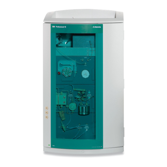
■■■■■■■■■■■■■■■■■■■■■■ 2.1 Front 2 Overview of the instrument Front Figure 1 Front 850 Professional IC – Anion – MSM-HC – MCS – LP Gradient Eluent degasser High pressure pump See Chapter 3.10, Page 37. See Chapter 3.12, Page 42. ■■■■■■■■... - Page 19 See Chapter 3.11, Page 38 For two additional eluents.(see Chapter 3.10, page 37) 15 Eluent aspiration tubing 6.1834.080 16 Connection tubing eluent degasser – high pressure pump 6.1834.090 17 Column inlet capillary 6.1831.150 ■■■■■■■■ 850 Professional IC–Anion – MSM-HC – MCS – LP Gradient...
-
Page 20: Rear
■■■■■■■■■■■■■■■■■■■■■■ 2.2 Rear Rear Figure 2 Rear 850 Professional IC Anion – MSM-HC – MCS – LP Gradient Knurled screws Vacuum connection For connecting further degassing chambers For fastening the rear panel (2- ) and han- in extension modules. dle (5- Labeled with Vacuum. - Page 21 For securing the vacuum pump when trans- chamber. porting the instrument. Labeled with Exhaust. 21 Drainage tubing connection 22 Rear panel For connecting a drainage tubing Removable. Access to the detector chamber. 6.1816.020 (9- ■■■■■■■■ 850 Professional IC–Anion – MSM-HC – MCS – LP Gradient...
- Page 22 ■■■■■■■■■■■■■■■■■■■■■■ 2.2 Rear CAUTION When connecting an instrument to the MSB connector (2-6) you must switch off the 850 Professional IC. ■■■■■■■■ 850 Professional IC–Anion – MSM-HC – MCS – LP Gradient...
-
Page 23: Installation
A large number of the capillary connections are already connected at the time the instrument is delivered. The 850 Professional IC – Anion – MSM-HC – MCS – LP Gradient is sup- plied the same way as an isocratic instrument, i.e. it can be put into oper- ation with minimum effort for usage with only one eluent. - Page 24 Connect a part of the 6.1803.040 sample aspirating capillary with ■ a 6.2744.090 long pressure screw to the input of the sample degasser. Guide the other end out of the instrument through a capillary feed-through. ■■■■■■■■ 850 Professional IC–Anion – MSM-HC – MCS – LP Gradient...
- Page 25 Install the separation column (see "Connecting and rinsing the ■ separation column", page 73). 10 Conditioning the instrument See Chapter 4.1, Page 74 The instrument is now ready for measuring samples. ■■■■■■■■ 850 Professional IC–Anion – MSM-HC – MCS – LP Gradient...
-
Page 26: Installation Of The Low Pressure Gradient
3.3 Installation of the low pressure gradient Installation of the low pressure gradient The installation of the 850 Professional IC – Anion – MSM-HC – MCS – LP Gradient must be adjusted slightly in order to be operated as a low pres- sure gradient system. -
Page 27: Installation Diagram
Most of the capillaries are already pre-installed at the time the instrument is delivered. Capillaries on which nothing needs to be done at the time of initial installation are not numbered in the diagram. ■■■■■■■■ 850 Professional IC–Anion – MSM-HC – MCS – LP Gradient... -
Page 28: Figure 3 Installation Diagram
Installation diagram Eluent aspiration tubing 6.1834.080 Tubing connection 6.1834.120 Three aspiration tubings for three different Connection Eluent degasser – Mixing valve eluents (see Chapter 3.9.1, page 33). input A ■■■■■■■■ 850 Professional IC–Anion – MSM-HC – MCS – LP Gradient... - Page 29 20 PEEK pressure screws, long 6.2744.070 6.2744.090 21 Tubing olive 6.2744.030 22 Pump tubing connection with safety device 6.2744.180 You will find detailed descriptions of the individual installation steps in the following chapters. ■■■■■■■■ 850 Professional IC–Anion – MSM-HC – MCS – LP Gradient...
-
Page 30: Setting Up The Instrument
Generally speaking, capillary connections between two components of an IC instrument are made up of one connection capillary and two pressure screws with which the capillary is connected to the respective compo- nents. ■■■■■■■■ 850 Professional IC–Anion – MSM-HC – MCS – LP Gradient... -
Page 31: Figure 4 Connection Of Capillaries With Pressure Screws
6.1831.010 PEEK capillary (internal diameter of 0.25 mm) for the entire ■ high pressure range. 6.1831.030 PEEK capillary (internal diameter of 0.75 mm) for sample ■ handling in the ultra trace range. ■■■■■■■■ 850 Professional IC–Anion – MSM-HC – MCS – LP Gradient... -
Page 32: Rear Of The Instrument
6.2621.080 capillary cutter. Rear of the instrument 3.7.1 Rollers and handle In order to make transport easier, the instrument is equipped with rollers and a handle. ■■■■■■■■ 850 Professional IC–Anion – MSM-HC – MCS – LP Gradient... -
Page 33: Figure 5 Rollers And Handle
Removing handle 1 Loosen knurled screws (5-1) and remove handle (5-2). Removing rollers Proceed as follows to remove the rollers: 1 Remove knurled screws (5-3). 2 Remove roller holder (5-5). ■■■■■■■■ 850 Professional IC–Anion – MSM-HC – MCS – LP Gradient... -
Page 34: Figure 6 Handle As Mpak Holder
Figure 6 Handle as MPak holder Knurled screws Handle Extended. As holder for MPaks (eluent bag). For fastening the handle (6- ) and the rear panel of the detector chamber. ■■■■■■■■ 850 Professional IC–Anion – MSM-HC – MCS – LP Gradient... -
Page 35: Positioning And Connecting The Detector
For fastening the removable rear panel. Removable Cable feed-throughs Capillary feed-throughs For feeding through detector cables. Detector connection sockets Labeled with Detector 1 and Detector 2 for connecting Metrohm detectors. ■■■■■■■■ 850 Professional IC–Anion – MSM-HC – MCS – LP Gradient... - Page 36 MagIC Net method. Recommendation: Use Detector 1 as standard. In the AnCat sys- tem with 2 detectors: Detector 1 for anions, Detector 2 for cati- ons. ■■■■■■■■ 850 Professional IC–Anion – MSM-HC – MCS – LP Gradient...
-
Page 37: Transport Locking Screws
Connecting the leak sensor 1 Plug the leak sensor connector plug (8-2) into the leak sensor con- nector socket (8-1) on the rear of the instrument (see Figure 8, page 28). ■■■■■■■■ 850 Professional IC–Anion – MSM-HC – MCS – LP Gradient... -
Page 38: Drainage Tubing
This ensures that any leaks in the system will be detected by the leak sensor. ■■■■■■■■ 850 Professional IC–Anion – MSM-HC – MCS – LP Gradient... -
Page 39: Figure 9 Drainage Tubing
Y connector 6.1807.010 Drainage tubing For connecting the two drainage tubings Section of the 6.1816.020 silicon tubing. Guides escaped fluid to the leak sensor. ) and (9- ■■■■■■■■ 850 Professional IC–Anion – MSM-HC – MCS – LP Gradient... -
Page 40: Capillary And Cable Feed-Throughs
They are located on the doors (see Figure 10, page 31), on the rear panel (see Figure 7, Page 25) or below the covering plate or above the base tray (see Figure 11, Page 32). ■■■■■■■■ 850 Professional IC–Anion – MSM-HC – MCS – LP Gradient... -
Page 41: Figure 10 Capillary Feed-Throughs On The Doors
Do not feed capillaries through the Luer connectors (10-1). The capillaries are fastened with PEEK pressure screws (10-3) from inside to the Luer connector. From outside, liquid can be aspirated or injected with a syringe. ■■■■■■■■ 850 Professional IC–Anion – MSM-HC – MCS – LP Gradient... -
Page 42: Figure 11 Capillary Feed-Throughs Base Tray/Covering Plate
10 Capillary feed-through Lower. From front to right. Lower. From front to back. 11 Capillary feed-through 12 Capillary feed-through Lower. From front to back. Lower. From front to left. ■■■■■■■■ 850 Professional IC–Anion – MSM-HC – MCS – LP Gradient... -
Page 43: Eluent
Slide tubing nipple (12-2) and O-ring (12-3) onto the eluent aspi- ■ ration tubing (12-1). Push eluent aspiration tubing (12-1) through the bottle attach- ■ ment (12-4) and screw tight. ■■■■■■■■ 850 Professional IC–Anion – MSM-HC – MCS – LP Gradient... -
Page 44: Figure 12 Installing Eluent Bottle Attachment
3 Mounting aspiration filter Insert filter holder (13-1) into the aspiration filter (13-2) and screw ■ tight. Figure 13 Mounting aspiration filter Filter holder Aspiration filter 6.2821.090 From accessory set 6.2744.210. ■■■■■■■■ 850 Professional IC–Anion – MSM-HC – MCS – LP Gradient... -
Page 45: Figure 14 Installing Tubing Weighting And Aspiration Filter
The end of the tubing must still touch the base of the filter. Figure 15 Eluent aspiration tubing fully equipped. 5 Mounting eluent aspiration tubing to the eluent bottle Insert the eluent aspiration tubing into the eluent bottle (16-10). ■ ■■■■■■■■ 850 Professional IC–Anion – MSM-HC – MCS – LP Gradient... -
Page 46: Figure 16 Eluent Bottle - Connected
Eluent bottle – connected Eluent aspiration tubing 6.1834.080 Adsorber tube 6.1609.000 For aspirating the eluent. Pre-installed. Wadding adsorber Adsorbs CO from the air (e.g. Merck soda lime with indicator, no. 6839.10). ■■■■■■■■ 850 Professional IC–Anion – MSM-HC – MCS – LP Gradient... -
Page 47: Eluent Degasser
The following installation instructions need not be carried out at the time of initial installation. Connecting the eluent degasser Figure 17 Eluent degasser Eluent degasser input Eluent degasser output ■■■■■■■■ 850 Professional IC–Anion – MSM-HC – MCS – LP Gradient... -
Page 48: Low Pressure Gradient
10…90%. However, depending on the installed pump head and the set flow, the smallest possible eluent per- centage can vary (see Table 1, page 39). ■■■■■■■■ 850 Professional IC–Anion – MSM-HC – MCS – LP Gradient... - Page 49 C. Pre-installed. Eluent inlet C Connection tubing 6.1834.100 Connects the eluent degasser (18- ) and the mixing valve input B. Pre-installed. Eluent inlet B Eluent inlet A Eluent outlet ■■■■■■■■ 850 Professional IC–Anion – MSM-HC – MCS – LP Gradient...
-
Page 50: Figure 19 Connecting Mixing Coil For Low Pressure Gradients
2 Fasten the other end of the mixing coil for low pressure gradients (19-3) with the 6.2744.070 short PEEK pressure screw (19-4) directly to the inlet valve holder of the high pressure pump (see Chapter 3.12.2, page 43). ■■■■■■■■ 850 Professional IC–Anion – MSM-HC – MCS – LP Gradient... -
Page 51: Figure 20 Connecting Eluent Connection Tubings
(20-4). Carefully tighten the clamping screw (20-5) with 6.2621.050 ■ wrench. 2 Repeat Step 1 with the other two eluent connection tubings (20-2) and (20-3). ■■■■■■■■ 850 Professional IC–Anion – MSM-HC – MCS – LP Gradient... -
Page 52: High Pressure Pump
Figure 21 Capillary connections high pressure pump/purge valve Connection capillary PEEK pressure screw, short 6.2744.070 PEEK capillary connects main piston and auxiliary piston. Outlet valve holder Pump head 6.2824.110 ■■■■■■■■ 850 Professional IC–Anion – MSM-HC – MCS – LP Gradient... -
Page 53: Connecting Low Pressure Gradient
2 Connecting mixing coil for low pressure gradients Screw the end of the mixing coil for low pressure gradients (22-3) ■ with the shorter pressure screw (22-2) to the inlet valve holder (22-1). ■■■■■■■■ 850 Professional IC–Anion – MSM-HC – MCS – LP Gradient... -
Page 54: Deaerating The High Pressure Pump
Deaerate the high pressure pump as follows (see Figure 23, page 45): Deaerating the high pressure pump The instrument must be connected to the PC and switched on to deaerate the high pressure pump. ■■■■■■■■ 850 Professional IC–Anion – MSM-HC – MCS – LP Gradient... -
Page 55: Figure 23 Deaerating The High Pressure Pump
4 Setting the flow rate Start MagIC Net (if not yet started). ■ Ensure that the eluent aspiration tubing is immersed sufficiently in ■ the eluent. Let the high pressure pump run. ■ ■■■■■■■■ 850 Professional IC–Anion – MSM-HC – MCS – LP Gradient... -
Page 56: Inline Filter
The following installation instructions need not be carried out at the time of initial installation. Installing the inline filter CAUTION Observe the flow direction marked on the filter housing for the connec- tion of the inline filter. ■■■■■■■■ 850 Professional IC–Anion – MSM-HC – MCS – LP Gradient... -
Page 57: Pulsation Damper
(see Chapter 3.12, page 42) and injection valve (see Chapter 3.16, page 50). The pulsation damper can be operated in both directions. ■■■■■■■■ 850 Professional IC–Anion – MSM-HC – MCS – LP Gradient... -
Page 58: Sample Degasser
NOTE When using the sample degasser, the rinsing time extends by at least 2 minutes. ■■■■■■■■ 850 Professional IC–Anion – MSM-HC – MCS – LP Gradient... - Page 59 4 Guide the other end of the connection capillary out of the instrument through a capillary feed-through. CAUTION If the sample degasser is not used, the input and output must be sealed with the 6.2744.220 thread stoppers. ■■■■■■■■ 850 Professional IC–Anion – MSM-HC – MCS – LP Gradient...
-
Page 60: Injection Valve
Connection capillary Connection capillary Connected to connector 1. Carries sample to Connected to connector 2. Carries sample to the injection valve. the waste container. PEEK pressure screw 6.2744.010 ■■■■■■■■ 850 Professional IC–Anion – MSM-HC – MCS – LP Gradient... -
Page 61: Mode Of Operation Of The Injection Valve
The following figure provides a schematic display of the flow paths of the two valve positions. Figure 28 Injection valve – Positions Position FILL Position INJECT ■■■■■■■■ 850 Professional IC–Anion – MSM-HC – MCS – LP Gradient... -
Page 62: Selecting The Sample Loop
3.17 Column thermostat The column thermostat controls the temperature of the column and elu- ent channel and thus ensures stable measuring conditions. It provides space for 2 separation columns. ■■■■■■■■ 850 Professional IC–Anion – MSM-HC – MCS – LP Gradient... - Page 63 With column recognition. The column thermostat contains two column holders (29-3) equipped with chip recognition. The separation columns can be clicked into the col- umn holder with the chip. ■■■■■■■■ 850 Professional IC–Anion – MSM-HC – MCS – LP Gradient...
- Page 64 After initial start-up: ■ Fasten the guard column (if used) or the separation column with a 6.2744.010 pressure screw to the end of the column input capil- lary. ■■■■■■■■ 850 Professional IC–Anion – MSM-HC – MCS – LP Gradient...
-
Page 65: High Capacity Metrohm Suppressor Module
The three inputs and outputs of the suppressor units numbered with 1, 2 and 3 on the MSM-HC each have 2 fixed mounted PTFE capillaries (see Figure 30, page 56). ■■■■■■■■ 850 Professional IC–Anion – MSM-HC – MCS – LP Gradient... -
Page 66: Figure 30 Msm-Hc - Connectors
IC system as follows: CAUTION As the PTFE capillaries are very soft, the pressure screws should not be overtightened. Flattened capillaries can be shortened with the help of a capillary cutter. ■■■■■■■■ 850 Professional IC–Anion – MSM-HC – MCS – LP Gradient... - Page 67 Guide the other end of the outlet capillary labeled with Waste ■ into a sufficiently large waste container and fasten it there. The rinsing and regeneration solutions are pumped with a peristaltic pump (see Chapter 3.19, page 58). ■■■■■■■■ 850 Professional IC–Anion – MSM-HC – MCS – LP Gradient...
-
Page 68: Peristaltic Pump
(31-2), so that the rollers (31-3) push the liquid for- ward in the pump tubing. Figure 31 Peristaltic pump Knurled screw in the mounting pin Roller hub Rollers Cartridge holder Tubing cartridges 6.2755.000 Contact pressure lever Snap-action lever ■■■■■■■■ 850 Professional IC–Anion – MSM-HC – MCS – LP Gradient... -
Page 69: Installing The Peristaltic Pump
(31-1). 2 Connecting the aspiration side Place a 6.2744.034 tubing olive (32-2) on the aspiration side of the pump tubing. ■■■■■■■■ 850 Professional IC–Anion – MSM-HC – MCS – LP Gradient... -
Page 70: Figure 33 Install Pump Tubing Connection With Filter
Place the tubing olive with filter holder (33-3) onto the pump tub- ■ ing. Screw the union nut (33-1) onto the tubing olive (33-3). ■ Case B: 6.2744.160 pump tubing connection without filter: ■■■■■■■■ 850 Professional IC–Anion – MSM-HC – MCS – LP Gradient... -
Page 71: Figure 34 Install Pump Tubing Connection Without Filter
Screw the respective capillaries tightly to the two tubing olives ■ with PEEK pressure screws (32-1). Table 2 Pump tubings and suitable adapters Pump tubing Adapter 6.1826.020 (blue/blue) 6.1826.310 (orange/green) 6.1826.320 (orange/yellow) 6.1826.330 (orange/white) ■■■■■■■■ 850 Professional IC–Anion – MSM-HC – MCS – LP Gradient... - Page 72 NOTE Pump tubings are consumable material. The service life of the pump tubings depends on the contact pressure amongst other factors. ■■■■■■■■ 850 Professional IC–Anion – MSM-HC – MCS – LP Gradient...
-
Page 73: Metrohm Co Suppressor (Mcs)
The MCS is connected between the MSM (see Chapter 3.18, page 55) and detector. Figure 35 MCS – connection MCS input MCS output Connection to the MSM. Connection to the detector. ■■■■■■■■ 850 Professional IC–Anion – MSM-HC – MCS – LP Gradient... -
Page 74: Installing The Adsorption Cartridges
6.2837.000 CO adsorption cartridge (36-4). Moisture can block the CO adsorption cartridge. In order to prevent this, a 6.2837.010 H O adsorption cartridge (36-7) is connected upstream. ■■■■■■■■ 850 Professional IC–Anion – MSM-HC – MCS – LP Gradient... -
Page 75: Figure 36 Adsorption Cartridge Holder
Connection to the MCS. Corresponds to (35- Installing the adsorption cartridges 1 Preparing the adsorption cartridge holder Push the 4 clips (36-3) into the slot of the adsorption cartridge holder (36-8). ■■■■■■■■ 850 Professional IC–Anion – MSM-HC – MCS – LP Gradient... -
Page 76: Conductivity Detector
The conductivity detector continuously measures the conductivity of the liquid passing through and indicates these signals in digital form (DSP – Digital Signal Processing). The conductivity detector exhibits outstanding thermal stability and thus guarantees reproducible measuring conditions. ■■■■■■■■ 850 Professional IC–Anion – MSM-HC – MCS – LP Gradient... -
Page 77: Figure 37 Conductivity Detector Front
■■■■■■■■■■■■■■■■■■■■■■ 3 Installation Figure 37 Conductivity detector front IC detector 1.850.9010 Opening for temperature sensor Detector input capillary Permanently installed. ■■■■■■■■ 850 Professional IC–Anion – MSM-HC – MCS – LP Gradient... -
Page 78: Figure 38 Conductivity Detector Rear
Connecting the detector input capillary to the MCS Fasten the detector input capillary (39-1) using a 2.2744.090 long ■ PEEK pressure screw (39-2) on the output of the MCS (39-3). ■■■■■■■■ 850 Professional IC–Anion – MSM-HC – MCS – LP Gradient... -
Page 79: Connecting The Instrument
Which mains cable is supplied depends on the location: 6.2122.020 with plug SEV 12 (Switzerland, …) ■ 6.2122.040 with plug CEE(7), VII (Germany, …) ■ 6.2122.070 with plug NEMA 5-15 (USA, …) ■ ■■■■■■■■ 850 Professional IC–Anion – MSM-HC – MCS – LP Gradient... -
Page 80: Guard Column
NOTE Information regarding which guard column is suitable for your separa- tion column can be found in the Metrohm IC Column Program (which is available from your Metrohm agent), the information sheet provided along with your separation column, the product information on the separation column at http://www.metrohm.com... - Page 81 Start the high pressure pump and rinse the guard column approx. ■ 5 minutes with eluent. Set the flow according to the correspond- ing column information sheet. Switch off the high pressure pump again. ■ ■■■■■■■■ 850 Professional IC–Anion – MSM-HC – MCS – LP Gradient...
-
Page 82: Separation Column
(observe manufacturer's data). You can find the separation columns and guard columns currently avail- able from Metrohm in the Metrohm IC Column Program, or in the Inter- net at http://www.metrohm.com in the product area Ion Chromatogra- phy. - Page 83 The iColumns are equipped with a chip on which their operating data is saved. The chip has to be hooked into the chip holder provided for this so that the column recognition can function. ■■■■■■■■ 850 Professional IC–Anion – MSM-HC – MCS – LP Gradient...
-
Page 84: Start-Up
Switch on the instrument. ■ 3 Deaerating the high pressure pump Deaerate the high pressure pump(s) via the purge valve (see ■ Chapter 3.12.3, page 44). ■■■■■■■■ 850 Professional IC–Anion – MSM-HC – MCS – LP Gradient... -
Page 85: Conditioning
(see column information sheet and chip data set). Start the PC program MagIC Net. ■ Open the Equilibration tab in MagIC Net. ■ Select (or create) a suitable method. ■ ■■■■■■■■ 850 Professional IC–Anion – MSM-HC – MCS – LP Gradient... - Page 86 4 Conditioning the system Rinse the system with eluent until the required stability of the base- line is attained (normally 30 minutes). The instrument is now ready for measuring samples. ■■■■■■■■ 850 Professional IC–Anion – MSM-HC – MCS – LP Gradient...
-
Page 87: Operation And Maintenance
Metrohm company. If working frequently with caustic and corrosive chemicals, a shorter main- tenance interval is recommended. The Metrohm service department offers every form of technical advice for maintenance and service of all Metrohm instruments. ■■■■■■■■... -
Page 88: Operation
Only use PEEK capillaries with an internal diameter of 0.25 mm in the high pressure range between the high pressure pump (see Chapter 3.12, page 42) and the detector. ■■■■■■■■ 850 Professional IC–Anion – MSM-HC – MCS – LP Gradient... -
Page 89: Door
Organic solvents The addition of an organic solvent (e.g. metha- nol, acetone, acetonitrile) to aqueous eluents generally accelerates lipophilic ions. ■■■■■■■■ 850 Professional IC–Anion – MSM-HC – MCS – LP Gradient... -
Page 90: Operation
These lead to contaminated valves, a rise in pressure and in extreme cases scratched pistons. It is therefore essential to ensure that no precipitates can occur (see Chapter 5.4.2.3, page 80). ■■■■■■■■ 850 Professional IC–Anion – MSM-HC – MCS – LP Gradient... -
Page 91: Maintenance
4 Remove pump head from the pump housing by loosening the 4 fas- tening screws (21-5) using the 6.2621.030 hexagon key. The main piston is on the left (viewed from the front), and the auxiliary piston is on the right. ■■■■■■■■ 850 Professional IC–Anion – MSM-HC – MCS – LP Gradient... -
Page 92: Figure 40 Removing Piston
Remove the zirconium oxide piston and lay on a tissue. ■ Remove the spring retainer, spring and the inner plastic sleeve ■ from the piston cartridge and lay by. ■■■■■■■■ 850 Professional IC–Anion – MSM-HC – MCS – LP Gradient... -
Page 93: Figure 41 Components Of The Piston Cartridge
Replacing the piston seal The 6.2617.010 special tool (see Figure 42, page 84) is necessary in order to remove the piston seal from the pump head. It consists of two ■■■■■■■■ 850 Professional IC–Anion – MSM-HC – MCS – LP Gradient... -
Page 94: Figure 42 Tool For Piston Seal 6.2617.010
Avoid touching the sealing surface in the pump head (21-4) with the tool. Screw the special tool for the piston seal (42-1) with the narrow side just as far into the piston seal as the same can be removed. ■■■■■■■■ 850 Professional IC–Anion – MSM-HC – MCS – LP Gradient... -
Page 95: Figure 43 Removing The Piston Seal
Guide the sleeve of the tool for the piston seal (42-2) with inserted piston seal into the pump head and press the seal with the wide end of the tool for the piston seal (42-1) into the pump head recess. ■■■■■■■■ 850 Professional IC–Anion – MSM-HC – MCS – LP Gradient... -
Page 96: Figure 45 Inserting The Piston Seal Into The Pump Head
1 Removing valves Unscrew the connection capillary for the auxiliary piston (21-1) ■ from the outlet valve holder. Unscrew the holders for the inlet and outlet valves and remove ■ valves. ■■■■■■■■ 850 Professional IC–Anion – MSM-HC – MCS – LP Gradient... -
Page 97: Figure 46 Removing Valves
Only if this cleaning is useless, dismantle the valves separately and clean the components. 3 Dismantling valve Dismantle every valve separately. NOTE For dismantling the valve the 6.2617.020 tool for valve cartridges is required. ■■■■■■■■ 850 Professional IC–Anion – MSM-HC – MCS – LP Gradient... -
Page 98: Figure 47 Dismantling Valve
The inlet valve and the outlet valve consist of the same, just differ- ■ ently arranged components (see Figure 48, page 89). ■■■■■■■■ 850 Professional IC–Anion – MSM-HC – MCS – LP Gradient... -
Page 99: Figure 48 Components Of The Inlet Valve And Outlet Valve
Insert the seal with the larger opening faced downwards into the ■ recess of the tool. Lay the other valve components above another in the correct ■ sequence (see Figure 48, page 89). ■■■■■■■■ 850 Professional IC–Anion – MSM-HC – MCS – LP Gradient... - Page 100 Insert the outlet valve into the outlet valve holder the way the seal ■ is visible. Screw the outlet valve holder into the top of the pump head and ■ tighten with a wrench (46-1). ■■■■■■■■ 850 Professional IC–Anion – MSM-HC – MCS – LP Gradient...
-
Page 101: Inline Filter
Housing of the inline filter. Part of the 6.2821.120 accessories. 6.2821.130 filter Filter screw Packaging contains 10 items. Screw of the inline filter. Part of the 6.2821.120 accessories. Connection capillaries ■■■■■■■■ 850 Professional IC–Anion – MSM-HC – MCS – LP Gradient... - Page 102 6 Rinsing the inline filter Dismantle the guard column (if present) and the separation col- ■ umn and replace with a 6.2744.040 coupling. Rinse the instrument with eluent. ■ ■■■■■■■■ 850 Professional IC–Anion – MSM-HC – MCS – LP Gradient...
-
Page 103: Inline Sample Preparation
1 Emptying the sample path Pump air through the sample path (pump tubing, tubing connec- tions, capillary in the degasser, sample loop) for several minutes until all liquid is displaced by the air. ■■■■■■■■ 850 Professional IC–Anion – MSM-HC – MCS – LP Gradient... - Page 104 A. The lower the ratio, the lower the sample carry-over. This ratio can be altered by varying the rinsing time – thus allowing the rinsing time required for the application to be ascertained. ■■■■■■■■ 850 Professional IC–Anion – MSM-HC – MCS – LP Gradient...
-
Page 105: Sample Degasser
The suppressor units must never be regenerated in the same flow direc- tion in which the eluent is pumped. Therefore always mount the inlet and outlet capillaries according to diagram outlined in figure 30. ■■■■■■■■ 850 Professional IC–Anion – MSM-HC – MCS – LP Gradient... -
Page 106: Maintenance
Regenerating the MSM-HC 1 Disconnecting the MSM-HC from the IC system Disconnect the MSM-HC from the separation column and MCS or ■ the detector. ■■■■■■■■ 850 Professional IC–Anion – MSM-HC – MCS – LP Gradient... - Page 107 Blockage of the MSM-HC which cannot be eliminated (solutions can ■ no longer be pumped through the MSM-HC). Jamming of the MSM-HC which cannot be eliminated (MSM-HC can ■ no longer be switched over). ■■■■■■■■ 850 Professional IC–Anion – MSM-HC – MCS – LP Gradient...
-
Page 108: Figure 50 Msm-Hc - Components
3 Cleaning the supply and discharge lines Connect in turn each of the 6 capillary tubings fastened on the ■ MSM-HC connecting piece (50-2) on the high pressure pump and pump through ultra pure water. ■■■■■■■■ 850 Professional IC–Anion – MSM-HC – MCS – LP Gradient... - Page 109 8 Connecting and conditioning the MSM-HC Reconnect the MSM-HC to the IC system. ■ Before switching the MSM-HC over for the first time, rinse the ■ three suppressor units with solution for 5 minutes. ■■■■■■■■ 850 Professional IC–Anion – MSM-HC – MCS – LP Gradient...
- Page 110 Clean the sealing surface of the new MSM-rotor A (50-3) with ■ ethanol using a lint-free cloth. 4 Inserting the new MSM-HC rotor A CAUTION An incorrectly inserted MSM rotor A (50-3) can be destroyed during start-up. ■■■■■■■■ 850 Professional IC–Anion – MSM-HC – MCS – LP Gradient...
-
Page 111: Peristaltic Pump
Therefore fully lift the tubing cartridges by loosening the snap- action lever (32-10) on the right-hand side if the peristaltic pump is to be turned off for a longer period. Once set, the contact pressure remains unaffected. ■■■■■■■■ 850 Professional IC–Anion – MSM-HC – MCS – LP Gradient... -
Page 112: Maintenance
6.1826.320 Pump tubing LFL PVC (Tygon) 0.48 mm For suppressor solutions, (orange/yellow), 3- acceptor solutions for stopper inline dialysis and for inline ultrafiltration. ■■■■■■■■ 850 Professional IC–Anion – MSM-HC – MCS – LP Gradient... -
Page 113: Figure 51 Pump Tubing Connection - Changing The Filter
6.2621.000 adjustable wrenches. 2 Replacing the filter Remove the old filter (51-2) with tweezers. ■ Place the new filter (51-2) flat in the tubing olive (51-1) with ■ tweezers. ■■■■■■■■ 850 Professional IC–Anion – MSM-HC – MCS – LP Gradient... -
Page 114: Replacing The Co 2 Adsorption Cartridge
1 Allow material to dry loose (not in cartridge) at 140 °C overnight and refill. Or dispose of the old material, and fill with new material. 2 Cover the packed material with wadding. ■■■■■■■■ 850 Professional IC–Anion – MSM-HC – MCS – LP Gradient... -
Page 115: Conductivity Detector
You can find detailed information on the separation columns available from Metrohm in the information sheet provided along with your separa- tion column, in the Metrohm IC-Column Program (available via your Metrohm agent) or in the Internet at http://www.metrohm.com... -
Page 116: Protection
Information regarding which guard column is suitable for your sepa- ration column can be seen in the Metrohm IC Column Program (which is available from your Metrohm agent), the information sheet provided... -
Page 117: Quality Management And Validation With Metrohm
Metrohm» available from your local Metrohm agent. Validation Please contact your local Metrohm agent for support in validating instru- ments and software. Here you can also obtain validation documentation to provide help for carrying out the Installation Qualification (IQ) and the Operational Qualification (OQ). -
Page 118: Troubleshooting
Condition (see Chapter 3.17, page 52) instru- attained. ment with the column thermostat switched on . Leak in the system. Check and seal connections (see Chapter 3.6, page 20). ■■■■■■■■ 850 Professional IC–Anion – MSM-HC – MCS – LP Gradient... - Page 119 5.13.1, page 104). exhausted. Pulsation damper not con- Connect the pulsation damper (see Chapter nected. 3.14, page 47). Pulsation damper not con- Connect pulsation damper (see Chapter 3.14, nected. page 47). ■■■■■■■■ 850 Professional IC–Anion – MSM-HC – MCS – LP Gradient...
- Page 120 Eluent – Blockage in the Check the eluent path. eluent path. Chromatograms Separation column – Regenerate separation column (see Chap- ■ have poor resolution diminished separating effi- ter 5.15.4, page 106). ciency. ■■■■■■■■ 850 Professional IC–Anion – MSM-HC – MCS – LP Gradient...
- Page 121 5.15.4, page 106). times in the chroma- ciency. Replace separation column (see "Connect- ■ tograms ing and rinsing the separation column", page 73). ■■■■■■■■ 850 Professional IC–Anion – MSM-HC – MCS – LP Gradient...
- Page 122 872 Extension Module: sealed. Connect an FEP tubing between the IC ■ instrument and the Extension Module and tighten both clamping screws until they seal. ■■■■■■■■ 850 Professional IC–Anion – MSM-HC – MCS – LP Gradient...
-
Page 123: Technical Specifications
Electronic, no calibration necessary Ambient conditions Operation Ambient tem- +5…+45 °C perature Humidity 20…80 % relative humidity Storage –20…+70 °C Ambient tem- perature Transport Ambient tem- –40…+70 °C perature ■■■■■■■■ 850 Professional IC–Anion – MSM-HC – MCS – LP Gradient... -
Page 124: Housing
Build-up time for < 60 s the vacuum Low pressure gradient Profile Step, linear, convex and concave Valve type Normally-closed Degasser One eluent degasser each for each of the three eluents. ■■■■■■■■ 850 Professional IC–Anion – MSM-HC – MCS – LP Gradient... -
Page 125: High Pressure Pump
The shutdown mechanism only becomes active 2 minutes after sys- ■ tem start The pump is automatically shut down after 3 piston strokes below ■ the minimum pressure limit ■■■■■■■■ 850 Professional IC–Anion – MSM-HC – MCS – LP Gradient... -
Page 126: 7.9 Sample Degasser
± 0.2 °C reproducibility Stability < 0.05 °C Heating up time < 30 minutes from 20 to 50 °C Cooling time < 40 minutes from 50 to 20 °C ■■■■■■■■ 850 Professional IC–Anion – MSM-HC – MCS – LP Gradient... -
Page 127: High Capacity Metrohm Suppressor Module (Msm-Hc)
Resistance to sol- No restriction (apart from PFC) vents Vacuum Microprocessor-controlled / stabilized Working range Build-up time < 30 s after start Capillary volume 400 µL Recommended 0.1…1.0 mL flow range ■■■■■■■■ 850 Professional IC–Anion – MSM-HC – MCS – LP Gradient... -
Page 128: Conductivity Measuring System
20…50 °C in increments of 5 °C ture Temperature < 0.001 °C stability Temperature 0…5 %/K adjustable, default 2.3 %/K compensation Heating up time < 30 minutes (40 °C) ■■■■■■■■ 850 Professional IC–Anion – MSM-HC – MCS – LP Gradient... -
Page 129: Mains Connection
2 DSUB-15-pin high density (female) Column recogni- 3 (including 2 in the column thermostat (see Chapter 3.17, page 52)) tion Leak sensor 1 jack plug Further connec- 1 DSUB 15-pin (female) ■ tions ■■■■■■■■ 850 Professional IC–Anion – MSM-HC – MCS – LP Gradient... -
Page 130: 7.18 Safety Specification
EN/IEC 61000-4-14 ■ NAMUR: 2006 ■ 7.20 Weight 29.4 kg (without accessories) 1.850.2210 1.850.9010 (con- 2.3 kg (with accessories) ductivity detector) Transport carriage 1.8 kg (rollers and han- dle) ■■■■■■■■ 850 Professional IC–Anion – MSM-HC – MCS – LP Gradient... -
Page 131: Conformity And Warranty
Name of commodity 850 Professional IC The 850 Professional IC is an intelligent instrument for ion chromatog- raphy analysis. This instrument has been built and has undergone final type testing... -
Page 132: Quality Management Principles
61010-1 and CSA-C22.2 No. 61010-1. This product is listed in Intertek’s Directory of Listed Products. Manufacturer Metrohm Ltd., CH-9101 Herisau/Switzerland Metrohm Ltd. is holder of the SQS-certificate ISO 9001:2000 Quality man- agement system for development, production and sales of instruments and accessories for ion analysis. Herisau, 27 October, 2008 D. -
Page 133: Warranty (Guarantee)
Components All components used in the Metrohm instruments have to satisfy the qual- ity standards that are defined and implemented for our products. Suppli- ers of components are audited by Metrohm as the need arises. - Page 134 ■■■■■■■■■■■■■■■■■■■■■■ 8.3 Warranty (guarantee) Faults arising from circumstances that are not the responsibility of Metrohm, such as improper storage or improper use, etc. are expressly excluded from the warranty. ■■■■■■■■ 850 Professional IC–Anion – MSM-HC – MCS – LP Gradient...
-
Page 135: Accessories
■■■■■■■■■■■■■■■■■■■■■■ 9 Accessories 9 Accessories CAUTION Subject to change without notice. Scope of delivery 2.850.2230 850 Professional IC – Anion – MSM-HC – MCS – LP Gradient Qty. Order no. Description 1.850.2230 850 Professional IC Anion – MSM-HC – MCS –... - Page 136 Inner diameter (mm): SGJ size: B-14/15 6.1803.020 PTFE capillary 0.97 mm i.d. / 5 m For all IC instruments Material: PTFE Outer diameter (mm): 1.57 Inner diameter (mm): 0.97 Length (m): ■■■■■■■■ 850 Professional IC–Anion – MSM-HC – MCS – LP Gradient...
- Page 137 Inner diameter (mm): Length (m): 6.1807.010 Y-connector for tubing 6-9 mm i.d. Connector for waste tubing 6.1815.010 Spiral band 0.5 m For holding together different cables or tubing. Length (m): ■■■■■■■■ 850 Professional IC–Anion – MSM-HC – MCS – LP Gradient...
- Page 138 Outer diameter (mm): Inner diameter (mm): Length (m): 6.1834.120 Tubing connection Degasser - mixing valve, 215 mm Connection between the Eluent Degasser and the low pressure mix- ing valve. Length (mm): ■■■■■■■■ 850 Professional IC–Anion – MSM-HC – MCS – LP Gradient...
- Page 139 USB connecting cable Length (m): 6.2322.010 PRIMUS multi anion standard solution: Promo 6.2617.010 Tool for piston seal For removing and assembling the piston seal for all standard pump heads ■■■■■■■■ 850 Professional IC–Anion – MSM-HC – MCS – LP Gradient...
- Page 140 Max. opening: 20 mm. For IC instruments Length (mm): 6.2621.030 Hexagon key 4 mm Length (mm): 6.2621.050 1/4 in. wrench For 1/4 in. screws. For IC instruments Length (mm): ■■■■■■■■ 850 Professional IC–Anion – MSM-HC – MCS – LP Gradient...
- Page 141 Hexagon key 3 mm for IC Sample Processors Length (mm): 6.2626.000 Drain nozzle (ProfIC) Drain nozzle for Professional IC instruments, for mounting on front panel 6.2739.000 Wrench For tightening connectors Length (mm): ■■■■■■■■ 850 Professional IC–Anion – MSM-HC – MCS – LP Gradient...
- Page 142 For IC instruments Material: PEEK Length (mm): 6.2744.034 Coupling nozzle - UNF 10/32, 2 pieces Connection pressure screw and pump tubing. 2 pieces. For IC instru- ments with peristaltic pumps ■■■■■■■■ 850 Professional IC–Anion – MSM-HC – MCS – LP Gradient...
- Page 143 PEEK capillaries (MCS and Sample degasser) Material: PEEK 6.2744.180 Pump tubing connector with security lock and filter For the connection of a pump tubing and a capillary with built-in fil- Material: PEEK ■■■■■■■■ 850 Professional IC–Anion – MSM-HC – MCS – LP Gradient...
- Page 144 Syringe 10 mL with Luer connection For various applications in IC and VA Material: Length (mm): Volume (mL): 6.2816.040 Purging needle With PTFE tubing and Luer connection. For syringes. For aspirating eluents. ■■■■■■■■ 850 Professional IC–Anion – MSM-HC – MCS – LP Gradient...
- Page 145 Spare filter for inline filter Spare filters for inline filter. 6.2837.000 adsorber cartridge Adsorber cartridge for purifying the air. 6.2837.010 O adsorption cartridge To CO Suppressor. Water adsorption cartridge for the aspirated air. ■■■■■■■■ 850 Professional IC–Anion – MSM-HC – MCS – LP Gradient...
-
Page 146: Optional Accessories
Manual for 850 Professional IC, 2.850.2230 – Anion – MSM-HC – MCS – LP Gradient, English Optional accessories 2.850.2230 850 Professional IC – Anion – MSM-HC – MCS – LP Gradient Order no. Description 6.2617.040 Tool for piston seal, macro For removing and assembling the piston seal for all macro pump heads 6.2741.040... - Page 147 21 CFR part 11 as well as GLP. Dialog languages: German, English, French, Chinese, Korean, Japanese and more. Client-Server version with 3 licen- ses. 6.9988.503 Validation Documentation for 850 (English / German) – CD ■■■■■■■■ 850 Professional IC–Anion – MSM-HC – MCS – LP Gradient...
-
Page 148: Index
"MSM-HC" .... 55 Aspiration ......33 Cable connector ....25 High pressure pump Production ......79 Capillary connector ..... 66 Installation ......42 Cell constant ....118 Maintenance ...... 80 ■■■■■■■■ 850 Professional IC–Anion – MSM-HC – MCS – LP Gradient... - Page 149 Reference conditions ....113 Interfaces ....... 119 Regeneration ......77 Further connections ..119 MSM-HC ......96 Leak sensor ...... 119 Oil ..........93 Rinsing Conductivity detector ..105 ■■■■■■■■ 850 Professional IC–Anion – MSM-HC – MCS – LP Gradient...
- Page 150 Peristaltic pump ....117 Installation ......72 Technical Specifications Protection ....2, 47, 106 MSM-HC ......117 Warranty ........ 123 Regeneration ....106 Temperature ......113 Rinsing ....... 73 ■■■■■■■■ 850 Professional IC–Anion – MSM-HC – MCS – LP Gradient...
Need help?
Do you have a question about the 850 Professional IC and is the answer not in the manual?
Questions and answers