
Subscribe to Our Youtube Channel
Related Manuals for SystemAir SYSHP MINI 05 EVO-P Q


Summary of Contents for SystemAir SYSHP MINI 05 EVO-P Q
- Page 1 Air Conditioning SYSHP MINI 07-16 EVO-P Mini Heat Pump Monobloc Series 7,4 to 14,0 kW 8,5 to16,2 kW Engineering Data Manual...
- Page 2 CONTENTS Part 1 General Information ................3 Part 2 Engineering Data ................17 Part 3 Installation and Field Settings ............33...
- Page 4 Part 1 General Information 1 SYSHP MINI system ................... 4 2 Product lineup ..................6 3 Nomenclature ................... 6 4 System Design and Unit Selection ............7...
-
Page 5: Syshp Mini System
1 SYSHP MINI system 1.1 System Schematic SYSHP MINI is an integrated air to water heat pump system which is one-stop solution for space heating, space cooling and domestic hot water, The outdoor heat pump system extracts heat from the outdoor air and transfers this heat through refrigerant piping to the plate heat exchanger in the hydronic system. - Page 6 1.2 System Configurations SYSHP MINI can be configured to run with the electric heater either enabled or disabled and can also be used in conjunction with an auxiliary heat source such as a boiler. The chosen configuration affects the size of heat pump that is required. Three typical configurations are described below. Configuration 1: Heat pump only ...
-
Page 7: Product Lineup
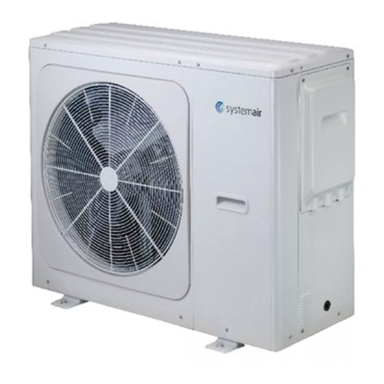
2 Product lineup Power Model Refrigerant Appearance supply(V/Ph/Hz) 220-240/1/50 SYSHP MINI 05 EVO-P Q SYSHP MINI 07 EVO-P Q 220-240/1/50 220-240/1/50 SYSHP MINI EVO-P Q 220-240/1/50 SYSHP MINI EVO-P Q 220-240/1/50 SYSHP MINI EVO-P Q 220-240/1/50 SYSHP MINI EVO-P Q... -
Page 8: System Design And Unit Selection
4 System Design and Unit Selection 4.1 Selection Procedure Step 1: Total heat load calculation Calculate conditioned surface area Select the heat emitters (type, quantity, water temperature and heat load) Step 2: System configuration Decide whether to include AHS and set AHS’s switching temperature Decide whether backup electric heater is enabled or disabled Step 3: Selection of outdoor units Determine required total heat load on outdoor units... - Page 9 4.2 SYSHP MINI Leaving Water Temperature (LWT) Selection The recommended design LTW ranges for different types of heat emitter are: For floor heating: 30 to 35⁰C For fan coil units: 30 to 45⁰C For low temperature radiators: 40 to 50⁰C 4.3 Optimizing System Design To get the most comfort with the lowest energy consumption with SYSHP MINI, it is important to take account of the following considerations:...
- Page 10 Part 2 Engineering Data 1 Specifications .................. 10 2 Electrical characteristic................16 3 Dimensions and Center of Gravity ............ 16 4 Operating Limits .................. 17 5 Capactiy Tables .................. 18 6 Hydronic Performance ................ 48 7 Sound Levels .................. 49 8 Climate Related Curves ................. 55...
- Page 11 1 Specifications 05 EVOP Q 07 EV0P Q Model SYSHP MINI 09 EVOP Q Power supply(V/Ph/Hz) 220-240/1/50 220-240/1/50 220-240/1/50 Capacity 6500 8400 10000 Heating A7W35 Rated input 1226 1663 2128 5.30 5.05 4.70 Capacity 6600 8500 10200 Heating A7W45 Rated input 1650 2237 2795...
- Page 12 5.09 5.19 5.08 Water outlet at 35℃ SEER Water outlet at 55℃ 7.81 8.09 8.31 Heating A7W35 Heating max Heating slince mode 1 Heating slince mode 2 Sound power level Cooling A35W18 Cooling max Cooling slince mode1 Cooling slince mode2 Compressor Type DC twin rotary...
- Page 13 Model SYSHP MINI 12 EVOP Q 14 EVOP Q 16 EVOP Q Power supply(V/Ph/Hz) 220-240/1/50 220-240/1/50 220-240/1/50 Capacity 12200 14100 16000 Heating A7W35 Rated input 2490 3000 3556 4.90 4.70 4.50 Capacity 12500 14500 16200 Heating A7W45 Rated input 3378 4085 4696 3.70...
- Page 14 Heating A7W35 Heating max Heating slince mode 1 Heating slince mode 2 Sound power level Cooling A35W18 Cooling max Cooling slince mode1 Cooling slince mode2 Compressor Type DC twin rotary DC twin rotary DC twin rotary Type DC motor DC motor DC motor Number Air flow...
- Page 15 Model SYSHP MINI 12 EVOP R 14 EVOP R 16 EVOP R Power supply(V/Ph/Hz) 380-415/3/50 380-415/3/50 380-415/3/50 Capacity 12200 14100 16000 Heating A7W35 Rated input 2490 3000 3556 4.90 4.70 4.50 Capacity 12500 14500 16200 Heating A7W45 Rated input 3378 4085 4696 3.70...
- Page 16 Heating A7W35 Heating max Heating slince mode 1 Heating slince mode 2 Sound power level Cooling A35W18 Cooling max Cooling slince mode1 Cooling slince mode2 Compressor Type DC twin rotary DC twin rotary DC twin rotary Type DC motor DC motor DC motor Number Air flow...
- Page 17 2 Electrical characteristics Outdoor unit Power current Compressor System Voltage Min. Max. TOCA SYSHP MINI 05 EVOP Q 220~240 10.5 0.17 SYSHP MINI 07 EVOP Q 220~240 14.5 10.5 0.17 SYSHP MINI 09 EVOP Q 220~240 10.5 0.17 SYSHP MINI 12 EVOP Q 220~240 0.17 SYSHP MINI 14 EVOP Q...
- Page 18 4 Operating Limits Heating operating limits 5 12 55 60 65 Cooling operating limits Domestic hot water operating limits 5 12 55 60 65 Abbreviations: T4: Outdoor temperature(°C) T1: Leaving water temperature (°C) IBH: Backup electric heater AHS: Additional heat source Notes: If IBH/AHS setting is valid, only IBH/AHS turns on; If IBH/AHS setting is invalid, only heat pump turns on, limitation and protection may occur. Heat pump turns off, only IBH/AHS turns on. (IBH can heat the water temperature up to 65℃, AHS can heat the water temperature up to 70℃) Operation range by heat pump with possible limitation and protection ...
- Page 19 5 Capactiy Tables 5.1 Heating Capacity Tables (Test standard:EN14511) SYSHP MINI 05 EVO‐P Q Part load: Maximum LWT 25 30 35 40 45 50 55 60 65 DB HC PI COP HC PI COP HC PI COP HC PI COP HC PI COP HC PI COP HC ...
- Page 20 Part load: 90% LWT 25 30 35 40 45 50 55 60 65 DB HC PI COP HC PI COP HC PI COP HC PI COP HC PI COP HC PI COP HC PI COP HC PI COP HC PI COP ‐25 3.47 ...
- Page 21 Part load: 30% LWT 25 30 35 40 45 50 55 60 65 DB HC PI COP HC PI COP HC PI COP HC PI COP HC PI COP HC PI COP HC PI COP HC PI COP HC PI COP ‐25 1.02 ...
- Page 22 SYSHP MINI 07 EVO‐P Q Part load: Maximum LWT 25 30 35 40 45 50 55 60 65 DB HC PI COP HC PI COP HC PI COP HC PI COP HC PI COP HC PI COP HC PI COP HC PI COP ...
- Page 23 Part load: 90% LWT 25 30 35 40 45 50 55 60 65 DB HC PI COP HC PI COP HC PI COP HC PI COP HC PI COP HC PI COP HC PI COP HC PI COP HC PI COP ‐25 3.82 ...
- Page 24 Part load: 30% LWT 25 30 35 40 45 50 55 60 65 DB HC PI COP HC PI COP HC PI COP HC PI COP HC PI COP HC PI COP HC PI COP HC PI COP HC PI COP ‐25 1.23 ...
- Page 25 SYSHP MINI 09 EVO‐P Q Part load: Maximum LWT 25 30 35 40 45 50 55 60 65 DB HC PI COP HC PI COP HC PI COP HC PI COP HC PI COP HC PI COP HC PI COP HC PI ...
- Page 26 Part load: 90% LWT 25 30 35 40 45 50 55 60 65 DB HC PI COP HC PI COP HC PI COP HC PI COP HC PI COP HC PI COP HC PI COP HC PI COP HC PI COP ‐25 3.95 ...
- Page 27 Part load: 30% LWT 25 30 35 40 45 50 55 60 65 DB HC PI COP HC PI COP HC PI COP HC PI COP HC PI COP HC PI COP HC PI COP HC PI COP HC PI COP 1.22 0.51 ...
- Page 28 SYSHP MINI 12 EVO‐P Q/R Part load: Maximum LWT 25 30 35 40 45 50 55 60 65 DB HC PI COP HC PI COP HC PI COP HC PI COP HC PI COP HC PI COP HC PI COP HC PI COP ...
- Page 29 Part load: 90% LWT 25 30 35 40 45 50 55 60 65 DB HC PI COP HC PI COP HC PI COP HC PI COP HC PI COP HC PI COP HC PI COP HC PI COP HC PI COP 6.03 2.69 ...
- Page 30 Part load: 30% LWT 25 30 35 40 45 50 55 60 65 DB HC PI COP HC PI COP HC PI COP HC PI COP HC PI COP HC PI COP HC PI COP HC PI COP HC PI COP ‐25 1.99 ...
- Page 31 SYSHP MINI 14 EVO‐P Q/R Part load: Maximum LWT 25 30 35 40 45 50 55 60 65 DB HC PI COP HC PI COP HC PI COP HC PI COP HC PI COP HC PI COP HC PI COP HC PI ...
- Page 32 Part load: 90% LWT 25 30 35 40 45 50 55 60 65 DB HC PI COP HC PI COP HC PI COP HC PI COP HC PI COP HC PI COP HC PI COP HC PI COP HC PI COP ‐25 6.45 ...
- Page 33 Part load: 30% LWT 25 30 35 40 45 50 55 60 65 DB HC PI COP HC PI COP HC PI COP HC PI COP HC PI COP HC PI COP HC PI COP HC PI COP HC PI COP ‐25 1.99 ...
- Page 34 SYSHP MINI 16 EVO‐P Q/R Part load: Maximum LWT 25 30 35 40 45 50 55 60 65 DB HC PI COP HC PI COP HC PI COP HC PI COP HC PI COP HC PI COP HC PI COP HC PI COP ...
- Page 35 Part load: 90% LWT 25 30 35 40 45 50 55 60 65 DB HC PI COP HC PI COP HC PI COP HC PI COP HC PI COP HC PI COP HC PI COP HC PI COP HC PI COP 7.05 3.26 ...
- Page 36 Part load: 30% LWT 25 30 35 40 45 50 55 60 65 DB HC PI COP HC PI COP HC PI COP HC PI COP HC PI COP HC PI COP HC PI COP HC PI COP HC PI COP ‐25 2.33 ...
- Page 37 5.2 Cooling Capacity Tables (Test standard:EN14511) SYSHP MINI 05 EVO‐P Q Part load: Maximum LWT 5 7 10 15 18 20 25 DB CC PI EER CC PI EER CC PI EER CC PI EER CC PI EER CC PI EER CC PI EER / / / ...
- Page 38 Part load: 70% LWT 5 7 10 15 18 20 25 DB CC PI EER CC PI EER CC PI EER CC PI EER CC PI EER CC PI EER CC PI EER / / / / / / / / / 3.19 ...
- Page 39 SYSHP MINI 07 EVO‐P Q Part load: Maximum LWT 5 7 10 15 18 20 25 DB CC PI EER CC PI EER CC PI EER CC PI EER CC PI EER CC PI EER CC PI EER / / / / / ...
- Page 40 Part load: 70% LWT 5 7 10 15 18 20 25 DB CC PI EER CC PI EER CC PI EER CC PI EER CC PI EER CC PI EER CC PI EER / / / / / / / / / 3.39 ...
- Page 41 SYSHP MINI 09 EVO‐P Q Part load: Maximum LWT 5 7 10 15 18 20 25 DB CC PI EER CC PI EER CC PI EER CC PI EER CC PI EER CC PI EER CC PI EER / / / / / ...
- Page 42 Part load: 70% LWT 5 7 10 15 18 20 25 DB CC PI EER CC PI EER CC PI EER CC PI EER CC PI EER CC PI EER CC PI EER / / / / / / / / / 3.45 ...
- Page 43 SYSHP MINI 12 EVO‐P Q/R Part load: Maximum LWT 5 7 10 15 18 20 25 DB CC PI EER CC PI EER CC PI EER CC PI EER CC PI EER CC PI EER CC PI EER / / / / / ...
- Page 44 Part load: 70% LWT 5 7 10 15 18 20 25 DB CC PI EER CC PI EER CC PI EER CC PI EER CC PI EER CC PI EER CC PI EER / / / / / / / / / 7.60 ...
- Page 45 SYSHP MINI 14 EVO‐P Q/R Part load: Maximum LWT 5 7 10 15 18 20 25 DB CC PI EER CC PI EER CC PI EER CC PI EER CC PI EER CC PI EER CC PI EER / / / / / ...
- Page 46 Part load: 70% LWT 5 7 10 15 18 20 25 DB CC PI EER CC PI EER CC PI EER CC PI EER CC PI EER CC PI EER CC PI EER / / / / / / / / / 7.97 ...
- Page 47 SYSHP MINI 16 EVO‐P Q/R Part load: Maximum LWT 5 7 10 15 18 20 25 DB CC PI EER CC PI EER CC PI EER CC PI EER CC PI EER CC PI EER CC PI EER / / / / / ...
- Page 48 Part load: 70% LWT 5 7 10 15 18 20 25 DB CC PI EER CC PI EER CC PI EER CC PI EER CC PI EER CC PI EER CC PI EER / / / / / / / / / 8.16 ...
- Page 49 6 Hydronic Performance SYSHP MINI 05 / 07 / 09 EVOP Q Water flow(m SYSHP MINI 12 / 14 / 16 EVOP Q SYSHP MINI 12 / 14 / 16 EVOP R Water flow(m ...
- Page 50 7 Sound Levels 7.1 Overall Table 2‐8.1: Sound pressure levels 2 Model name dB(A) SYSHP MINI 05 EVO‐P Q 48 SYSHP MINI 07 EVO‐P Q 51 SYSHP MINI 09 EVO‐P Q 53 SYSHP MINI 12 EVO‐P Q 56 SYSHP MINI 14 EVO‐P Q 58 SYSHP MINI 16 EVO‐P Q ...
- Page 51 7.2 Octave Band Levels (NR) SYSHP MINI 05 EVO‐P Q octave band levels Cooling in rated frequency Outdoor air temperature 35⁰C DB; EWT 12⁰C, LWT 7⁰C NR‐90 Cooling in rated frequency NR‐80 Outdoor air temperature 35⁰C NR‐70 DB; EWT 23⁰C, LWT 18⁰C NR‐60 ...
- Page 52 SYSHP MINI 09 EVO‐P Q octave band levels Cooling in rated frequency Outdoor air temperature 35⁰C DB; EWT 12⁰C, LWT 7⁰C NR‐90 Cooling in rated frequency Outdoor air temperature 35⁰C NR‐80 DB; EWT 23⁰C, LWT 18⁰C NR‐70 NR‐60 ...
- Page 53 SYSHP MINI 14 EVO‐P Q octave band levels Cooling in rated frequency Outdoor air temperature 35⁰C DB; EWT 12⁰C, LWT 7⁰C NR‐90 Cooling in rated frequency NR‐80 Outdoor air temperature 35⁰C DB; NR‐70 EWT 23⁰C, LWT 18⁰C NR‐60 Heating in rated frequency NR‐50 Outdoor ...
- Page 54 SYSHP MINI 12 EVO‐P Roctave band levels Cooling in rated frequency Outdoor air temperature 35⁰C DB; EWT 12⁰C, LWT 7⁰C NR‐90 Cooling in rated frequency NR‐80 Outdoor air temperature 35⁰C NR‐70 DB; EWT 23⁰C, LWT 18⁰C NR‐60 ...
- Page 55 SYSHP MINI 16 EVO‐P R octave band levels Cooling in rated frequency Outdoor air temperature 35⁰C DB; EWT 12⁰C, LWT 7⁰C NR‐90 Cooling in rated frequency NR‐80 Outdoor air temperature 35⁰C NR‐70 DB; EWT 23⁰C, LWT 18⁰C NR‐60 ...
- Page 56 8 Climate Related Curves The climate related curves can be selected in the user interface, MENU > PRESET TEMPERATURE > WEATHER TEMP. SET. WEATHER TEMP. SET menu If WEATHER TEMP. SET is active, the leaving water set temperature (T1s) will PRESE T TEMPER ATURE automatically change as outdoor ambient temperature (T4) changes. Totally 32 PRESET WEATHER weather temperature curves are already set by experienced engineer and one TEMP. TEMP.SET MODE personalized curve is available, which meets the diversified requirements of ZONE1 C-MODE LOW TEMP. temperature. ZONE1 H-MODE LOW TEMP. ZONE2 C-MODE LOW TEMP. The relationship between outdoor ambient temperature (T4) and leaving water set ZONE2 H-MODE LOW TEMP. temperature (T1s) is described as below. ...
- Page 57 High temperature curves for heating mode T1S(℃) Curve 1 Curve 2 Curve 3 Curve 4 Curve 5 Curve 6 Curve 7 Curve 8 T4(℃) ‐30 ‐25 ‐20 ‐15 ‐10 ‐5 Outdoor ambient temperature (⁰C ) Low temperature curves for cooling mode T1S(℃) Curve 1 Curve 2 Curve 3 Curve 4 Curve 5 Curve 6 Curve 7 Curve 8 T4(℃) ‐10 ‐5 Outdoor ambient temperature (⁰C ) ...
- Page 58 High temperature curves for cooling mode T1S(℃) Curve 1 Curve 2 Curve 3 Curve 4 Curve 5 Curve 6 Curve 7 Curve 8 T4(℃) ‐10 ‐5 Outdoor ambient temperature (⁰C ) The automatic setting curves are the ninth curve for cooling and heating mode. Automatic setting curve for heating mode Automatic setting curve for cooling mode T1S (T1S2) T1S (T1S2) T1SETC1 T1SETH1 T1SETC2 T1SETH2 T4C1 T4C2 T4H1 T4H2 ...
- Page 59 58 ...
- Page 60 Part 3 Installation and Field Settings 1 User Interface Field Settings ..............60 2 Operation parameter................79...
- Page 61 1 User Interface Field Settings Introduction During installation, the settings and parameters should be configured by the installer to suit the installation configuration, climate conditions and end-user preferences. The relevant settings are accessible and programmable through the FOR SERVICEMAN menu on the user interface. The user interface menus and settings can be navigated using the user interface’s touch-sensitive keys, as shown below:...
- Page 62 Menu Structure 7 OTHER HEATING SOURCE FOR SERVICEMAN 7.1 IBH FUNCTION 1 DHW MODE SETTING 7.2 IBH LOCATE 2 COOL MODE SETTING 7.3 dT1_IBH_ON 3 HEAT MODE SETTING 7.4 t_IBH_DELAY 4 AUTO MODE SETTING 7.5 T4_IBH_ON 5 TEMP. TYPE SETTING 1 DHW MODE SETTING 7.6 P_IBH1 6 ROOM THERMOSTAT...
- Page 63 FOR SERVICEMAN Menu FOR SERVICEMAN allows installers to input the system configuration and set the FOR SE RVICEMAN system parameters. To enter FOR SERVICEMAN, go to MENU > FOR SERVICEMAN. Please input password: Enter the password, using ◄ ► to navigate between digits and using ▼ ▲ to adjust the numerical values.
- Page 64 mode is on. If DHW mode is available and the space heating/cooling is OFF, then heat pump will change to DHW mode. If YES is selected in the DHW PRIORITY mode, then a maximum of three parameters(DHW PRIORITY TIME SET, t_DHWHP RESTRICT, t_DHWHP MAX) are needed to be set.
- Page 65 T5S_DISINFECT sets target water temperature of water tank of disinfect function. T5S_DI sets the DHW tank disinfection operation target temperature. Caution: during the disinfection operation (duration: t_DI_MAX) the domestic hot water temperature at the hot water taps will at times be equal to the value set for T5S_DI. DHW tank disinfection t_DI_HIGHTEMP sets that length of time that the DHW tank disinfection operation target temperature is maintained.
- Page 66 PUMP_D TIMER enable or disable the DHW pump run as timed and keeps running for PUMP_D RUNNING TIME PUMP_D RUNNING TIME set the certain time that the DHW pump will keep running PUMP_D DISINFECT enable or disable the DHW pump operates when heat pump is in disinfect mode and T5S_DI- T5≤2 ACS FUNCTION enable or disable the second water tank control T5_2 COOL MODE SETTING Menu MENU >...
- Page 67 t_INTERVAL_C sets the cooling mode compressor re-start delay. When the compressor stops running, it will not re-start until at least t_INTERVAL_C minutes have elapsed. T1SetC1 sets the water temperature 1 of personalized setting curve for cooling mode. T1SetC2 sets the water temperature 2 of personalized setting curve for cooling mode. T4C1 sets the ambient temperature 1 of personalized setting curve for cooling mode.
- Page 68 dTSH sets the temperature difference between the actual room temperature (Ta) and set room temperature (TS) above which the heat pump provides hot water to the space heating terminals. When TS – Ta ≥ dTSH the heat pump provides hot water to the space heating terminals and when Ta ≥...
- Page 69 TEMP. TYPE SETTING Menu MENU > FOR SERVICEMAN > TEMP. TYPE SETTING TEMP. TYPE SETTING menu The TEMP. TYPE SETTING is used for selecting whether the water flow temperature or 5 TEMP. TYPE SETTING room temperature is used to control the ON/OFF of the heat pump. 5.1 WATER FLOW TEMP.
- Page 70 ROOM THERMOSTAT Menu MENU > FOR SERVICEMAN > ROOM THERMOSTAT ROOM THERMOSTAT menu 6 ROOM THERMOSTAT As an alternative to control space heating/cooling modes according to the leaving 6.1 ROOM THERMOSTAT water temperature and/or the room temperature detected by the temperature sensor inside the user interface, separate room thermostat can be installed and used to control space heating/cooling modes.
- Page 71 dT1_IBH_ON sets the temperature difference between the heat pump leaving water set temperature (T1S) and the heat pump leaving water temperature (T1) above which the backup electric heater is on. When T1S - T1 ≥ dT1_IBH_ON the backup electric heater is on. t_IBH_DELAY sets the delay time for the electric heater to turn on after the compressor starts.
- Page 72 TBH FUNCTION enable or disable tank booster heater. dT5_TBH_OFF sets the temperature difference between the DHW set temperature (T5S) and the DHW tank water temperature (T5) below which the tank booster heater is not used. When T5 > Min(T5S+dT5_TBH_OFF, 65°C), the tank booster heater is off.
- Page 73 1.13 RESTORE FACTORY SETTINGS MENU > FOR SERVICEMAN > RESTORE FACTORY SETTINGS RESTORE FACTORY SETTINGS is used to restore all the parameters set in the user interface to factory defaults. On selecting YES, the process of restoring all settings to factory defaults begins and progress is displayed as a percentage. RESTORE FACTORY SETTINGS screens 10 RESTORE FACTORY SETTINGS 10 RESTORE FACTORY SETTINGS...
- Page 74 1.14.1 POINT CHECK The POINT CHECK menu is used to check the operation of individual components. Use ▼▲ to scroll to the components you want to check and press COMFIRM to toggle the on/off state of the component. If a valve does not turn on/off when its on/off state is toggled or if a pump/heater does not operate when turned on, check the component’s connection to the hydronic system main PCB.
- Page 75 1.14.4 COOL MODE RUNNING operation COOL MODE RUNNING display MENU > FOR SERVICEMAN > TEST RUN > COOL MODE RUNNING 11 TEST RUN TEST RUN IS ON. The COOL MODE RUNNING operation is used to check the operation of the system in COOL MODE IS ON.
- Page 76 1.15.2 PREHEATING FOR FLOOR MENU > FOR SERVICEMAN > SPECIAL FUNCTION > PREHEATING FOR FLOOR Before floor heating, if a large amount of water remains on the floor, the floor may be Preheating for floor menu warped or even rupture during floor heating operation, in order to protect the floor, 12.1 PREHEATING FOR FLOOR floor drying is necessary, during which the temperature of the floor should be 30°...
- Page 77 Phase 1: gradual temperature increase from a starting point of 25°C to the peak temperature Phase 2: maintain peak temperature Phase 3: gradual temperature decrease from the peak temperature to 45°C FLOOR DRYING UP settings WARM UP TIME(t_DRYUP) sets the duration of Phase 1. KEEP TIME(t_HIGHPEAK) sets the duration of Phase 2.
- Page 78 1.18 INPUT DEFINE MENU > FOR SERVICEMAN > INPUT DEFINE INPUT DEFINE sets sensors and functions to fulfill with installation. INPUT DEFINE INPUT DEFINE 15.1 M1M2 REMOTE ON/OFF 15.2 SMART GRID 15.3 T1T2 15.4 Tbt DEFROST 15.5 P_X PORT ADJUST M1M2 sets the remote control function of M1M2 for ON/OFF of heat pump or TBH SMART GRID sets whether SMART GRID control signal is connected to hydronic PCB.
- Page 79 1.20 HMI ADDRESS SET MENU > FOR SERVICEMAN > HMI ADDRESS SET HMI ADDRESS SET 17 HMI ADDRESS SET 17.1 HMI SET MASTER 17.2 HMI ADDRESS FOR BMS 17.3 STOP BIT ADJUST HMI SET sets the wired controller is master or slave. (0=MASTER, 1=SLAVE) When HMI SET is set to SLAVE, the controller can only switch the operation mode, turn on or off, set the temperature, and cannot set other parameters and functions.
- Page 80 2 Operation parameter MENU > OPERATION PARAMETER This menu is for installer or service engineer reviewing the operation parameters. The interface below is for reference and different units’ state correspond to different parameter values. Operation parameter OPPERATION PARAMETER OPPERATION PARAMETER OPPERATION PARAMETER COMP.
- Page 81 The following parameter ranges are used to roughly determine whether the system is running properly: Discharge temperature(Tp) for heating/DHW mode T4<-10℃ Twout+15<Tp<Tw_out+40 -10℃≤T4<10℃ Twout+10<Tp<Tw_out+35 10℃≤T4<25℃ Twout+10<Tp<Tw_out+30 T4≥25℃ Twout+10<Tp<Tw_out+28 Note: T4 means ambient temperature Tw_out means leaving water temperature. Discharge pressure(P1) for heating/DHW mode Tw_out(℃) 1750±...
- Page 83 Systemair srl Via XXV Aprile, 29 20825 Barlassina (MB) Italy Tel. +39 0362 680 1 Fax +39 0362 680 693 www.systemair.com...
Need help?
Do you have a question about the SYSHP MINI 05 EVO-P Q and is the answer not in the manual?
Questions and answers