Advertisement
Quick Links
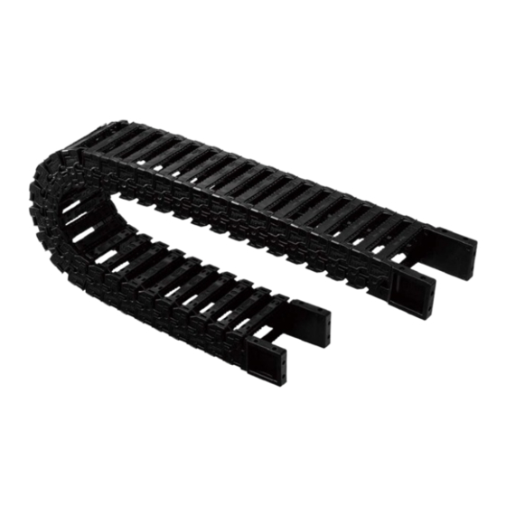
1 Construction/Part Names
3.
Arm
5.
Vertical divider
*Dividers can be one of the
following
depending
on
attachment direction
Locking type
Sliding type
2
Attaching Dividers
Dividers are attached when inserting cables and hoses.
Note: Dividers are attached on every two inner links. Check the amount attached at any one location.
(Dividers cannot be attached to bracket arms.)
Attaching locking dividers
Attach with the side with the "LOCK" stamp to the
inner link stay.
Tsubaki
Cableveyor
TKR15H22
4.
Travel end plastic bracket
3.
Arm
4.
Fixed end plastic bracket
*FO or FI
"LOCK"
Stay
Instruction Manual
*MO or MI
15
15
15
2.
Inner link
Note:
1. The TKR15H22 is not available with an odd number of links.
Only an even number of links is available.
2. One pitch of 15 mm is one link.
3. MO and FO are the same. MI and FI are the same
4. Cableveyor link's arms and bracket arms are the same.
Attaching sliding dividers
Attach with the side with the "TKR0150" stamp to the
inner link stay.
1
R
Outer Cir. Side
Inner Cir. Side
1.
Outer link
"TKR0150"
Stay
Advertisement

Subscribe to Our Youtube Channel
Related Manuals for Tsubaki Cableveyor TKR15H22


Summary of Contents for Tsubaki Cableveyor TKR15H22
- Page 1 Instruction Manual Tsubaki Cableveyor TKR15H22 1 Construction/Part Names Outer Cir. Side Travel end plastic bracket *MO or MI Vertical divider Inner Cir. Side *Dividers can be one of the following depending attachment direction Locking type Sliding type Outer link...
- Page 2 Opening and Removing Arms Follow the steps below to open and remove arms. Arms can be opened from either left or right. Note: Use a flat head screwdriver with a tip width of 3mm or less. 1. Insert a flat head screwdriver into the gap on the inner link side face and pry in the direction of the arrow to unlatch.
- Page 3 Shortening the Length of the Links Follow the steps below to shorten link length. 1. Remove the arms from the inner/outer side of the bracket and two arms (total of 5) from before and after the location where you wish to cut. (Refer to 3 above for removing arms.) 2.
- Page 4 Replace the bracket, and attach all arms and bracket arms (inner/outer side). (Refer to 5.3 for attaching.) Caution Depending on the application, pretension and sag may appear in the free span. However, if selected within Tsubaki’s performance graph then there will be no problems with use.
Need help?
Do you have a question about the Cableveyor TKR15H22 and is the answer not in the manual?
Questions and answers