Advertisement
Quick Links
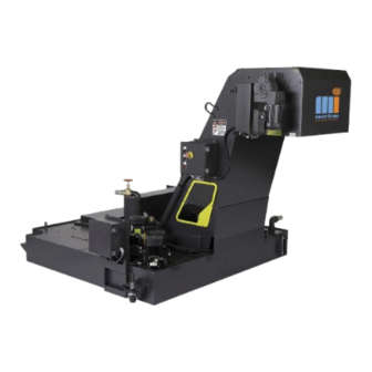
ConSep
Instruction Manual
Carefully read and understand the
•
instructions in this manual.
Fully understand the instructions written
•
in the manual before handling the
conveyor.
Retain the manual in a fixed place that it
•
is immediately available for your
reference whenever it is necessary.
2000ⅡWS
R
-125/200
Issued on 1 October, 2010
NOTICE
E43101-01
Advertisement

Related Manuals for Tsubaki ConSep2000 II WS-125


Summary of Contents for Tsubaki ConSep2000 II WS-125
- Page 1 E43101-01 ConSep 2000ⅡWS -125/200 Instruction Manual Issued on 1 October, 2010 NOTICE Carefully read and understand the • instructions in this manual. Fully understand the instructions written • in the manual before handling the conveyor. Retain the manual in a fixed place that it •...
- Page 3 CONTENTS LIMITED WARRANTY..................1 IMPORTANT INFORMATION................2 BILL OF MATERIAL OF ConSep2000 II WS ............3 WARNINGS AND SAFETY INSTRUCTIONS ............6 GENERAL INSTRUCTIONS ..................6 CAUTION........................7 WARNING LABELS ....................7 INSTRUCTIONS FOR REPAIR AND MAINTENANCE, MALFUNCTIONS..8 UNPACKING AND TRANSPORT ................9 UNPACKING .......................9 TRANSPORT ......................9 INSTALLATION AND COMMISSIONING OF ConSsp2000 II ......
- Page 4 10.1.1 Driving gearmotor ....................17 10.1.2 Main bearing......................17 10.1.3 Chain and belt ....................... 17 10.1.4 Filter check and change ..................17 10.1.5 Take-up adjustment ....................18 10.1.6 Belt shortening procedure..................20 10.1.7 Purge nozzle check and cleaning ................21 10.1.8 Disassembly and reassembly of the frame ............
- Page 5 1. LIMITED WARRANTY TSUBAKIMOTO MAYFRAN INC. (herein after referred to as we) will repair the conveyor only when we determine to be defective. The warranty period is within 1 year after the conveyor is shipped from our place or 3,000 operation hours whichever is shorter. In case the conveyor is delivered from a manufacturer of machine tools, please contact the supplier (manufacturer of machine tools) for the warranty period.
- Page 6 2. IMPORTANT INFORMATION Unfortunately, we cannot foresee all the dangers existing in the conveyor itself, dangers due to human error and dangers caused by the operating environment in which the conveyor is used. In addition, there are many cases of “not possible” and “must not”. All these cases cannot be listed in this manual and on the warning labels.
- Page 7 D25 (-125) Main shaft with sprocket Tsubakimoto mayfran D30 (-200) 8x7x22(-125) Parallel key 8x7x25(-200) Parallel key 8x7x52 CSM0X0-252 (-125) Hollow shaft gearmotor Tsubaki-Emerson CSM0X0-253 (-200) Detent pin D14x51.5 Cotter pin D4x25 Plate washer ----- ----- Bolt [for take-up base] M10x20,PW...
- Page 8 Description Type Make Inspection hole cover Tsubakimoto mayfran Inspection hole cover frame Tsubakimoto mayfran Bolt [for inspection cover] M6x10 31752 (-125) Hinged steel belt Tsubakimoto mayfran 50825 (-200) 2 or Pin link plate D-hole Tsubakimoto chain over RF2050R (-125) Roller link Tsubakimoto chain RF2080R (-200) Pin link plate...
- Page 10 4. WARNINGS AND SAFETY INSTRUCTIONS 4.1 GENERAL INSTRUCTIONS Put the included with CAUTION seals on easily-visible places on the conveyor. • All specifications and instructions in this manual must be followed at all times! Also, • fully understand the contents of the instructions before starting operation/maintenance. The proper functioning of safety equipment must always be ensured! •...
- Page 11 4.2 CAUTION ConSep2000 II WS should only be used for the purpose for which it is originally • intended ! The range of operating ambient temperature is between –10 and +40 . • Do not install the conveyor in any place where there is a possibility of rust due to high •...
- Page 12 5. INSTRUCTIONS FOR REPAIR AND MAINTENANCE, MALFUNCTIONS. Switch off the main switch before starting works! • Hang a warning tag from the main switch! • When canceling the safety devices, take appropriate measures so that any third • person should not touch easily! Turn off the power supply of the conveyor or pull out an electrical connector for the •...
- Page 13 6. UNPACKING AND TRANSPORT 6.1 UNPACKING ConSep 2000 II WS systems are usually supplied in one piece. According to the wishes of the customer, or in case of excessive lengths, these conveyors can be delivered in several sections. The hinged roller is packed on (a) palette(s) or in a crate. Small parts such as screws are included in (a) bag(s) or (a) box(es)..
- Page 14 7. INSTALLATION AND COMMISSIONING OF ConSsp2000 II WARNING Installation shall be done by a qualified person with technical knowledge. If the installation is not done appropriately, some serious accident may occur. Ensure that the system is installed in a stable and safe position. •...
- Page 15 Check the following before the operation. • (1) The side plates of the conveyor belt must be parallel to one another in direction of transport. If there is too much play or if the side plates are not properly aligned, the material being transported will get jammed.
- Page 16 8. STARTING UP ConSsp2000 II WS 8.1 GENERAL FUNCTIONS Make sure that the EMERGENCY STOP press button is released. ConSep2000 II WS system is now ready to be started up. 8.1.1 Operation without any object to be transferred After operating the conveyor without any object to be transferred, start operating with objects.
- Page 17 Fig.2...
- Page 18 8.3 Safety devices 8.3.1 Emergency STOP button (option) If serious danger is likely to occur or if there is a possibility it may occur while operating the conveyor, push the EMERGENCY STOP button to immediately stop the conveyor, prohibiting the conveyor operation. When the EMERGENCY STOP button is pulled (the button may be of turn-reset type), the emergency stop state is canceled and the conveyor can be operated again.
- Page 19 8.5 INSPECTION WINDOW Inspection window is made of PVC, therefore may be corroded by contents of the coolant. Get ‘Material Safety Data Sheet (MSDS)’ from coolant’s maker and confirm ‘MSDS’. 8.6 PRECAUTIONS FOR HANDLING TRANSFERRED OBJECTS ON THE CONVEYOR Returning transferred objects from the chip box at the discharge part of the conveyor Replace the chip box before objects discharged touch the surface of the return side belt.
- Page 20 When machining hard materials When you machined the materials which will be work-hardened (e.g. the following materials), the frame materials such as a rail and bottom pan may considerably be worn. Bearing steel (SUJ) High carbon chromium bearing steel Nickel chrome molybdenum steel (SNCM) Ceramics Nickel chrome steel (SNC) Too much scale build up on the surface (oxide film)
- Page 21 10.1.1 Driving gearmotor The gearmotor was designed specifically for our smaller conveyors. 10.1.1.1 Lubrication The reduction gear is factory-sealed in high quality lubricant and thus requires no filling. 10.1.1.2 Allowable temperature Allowable temperature for the reduction gear and motor are as follows: Reduction gear ·················...
- Page 22 (5) Set a new filter on the filter frame and lay the retainer ‘A‘ on top of it. Then, secure the retainer ’A’ with bolts. Wind the filter tightly around the frame to eliminate all slack and bunching. (6) Similarly, lay the retainer ‘B’ on top of filter. (7) Attach the hose bands.
- Page 23 10.1.5.2 Adjustment procedures (1) Loosen the bolts locking down the head end cover, the movable chain guide and the head end panel. Then remove these parts from the head panel. Head end cover Movable chain guide Head end panel Bolt (A) Take-up unit Take-up bolt Fig.5...
- Page 24 10.1.6 Belt shortening procedure If the belt tension is not enough even after the take-up bolt is adjusted, shorten the belt as follows. (1) Remove each part according to the steps (1) to (4) of “10.1.8.1 Disassembly.” (2) Move the belt joint part to the object discharge part. NOTICE A set of belt joint parts is provided at 1 or 2 places on the whole circumference of conveyor.
- Page 25 10.1.7 Purge nozzle check and cleaning Check and clean the Purge nozzle three month to six months, as explained here following: Check and clean interval is changes. Take cleaning action in a timely. (1) Remove the Purge nozzle, from the Elbow. Check the screen and clean in case of clogging.
- Page 26 10.1.8 Disassembly and reassembly of the frame 10.1.8.1 Disassembly The inside of the conveyor is all protected with the frame. To check worn condition of parts inside the frame, rollers and chain wheels, inspect and clean the inside of the frame once or twice a year.
- Page 27 NOTICE When the head of the belt pin tapped by a wooden hammer is warped, remove the warped part with files, etc. It is recommended to put the joint belt pin, which has been pulled out, through the hinge ring and roller link in advance to facilitate pulling out / insertion of the link plate.
- Page 28 10.1.10 Maintenance and check items This section describes the list of the maintenance / inspection items for the conveyor according to the frequency. Change the frequency as per the operating time and kinds of materials. (1) Everyday --------assuming that the operation is performed 10 hours a day. (2) Every month----assuming that the operation is performed 20 days a month.
- Page 29 10.1.10.3 Annual inspection item When performing annual inspection, disassemble the conveyor referring to “10.1.8.1 Disassembly.” Inspection item Trouble confirmation method Countermeasure Is the rail not worn out? Measure with a caliper, etc. When the rail is worn out to 1/3 in thickness, contact us.
- Page 30 11. TROUBLESHOOTING 11.1 Safety precaution Most of the accidents occur when troubleshooting is performed. When troubleshooting as per 11.2, follow the instructions in the section “4.WARNINGS_AND_SAFETY_INSTRUCTIONS”. If you think that you cannot perform the troubleshooting, contact us. 11.2 Troubleshooting when the conveyor comes to a sudden stop 11.2.1 For shock relay (Electrical/CSM type hollow shaft gear motor) In case of the operating conveyor stops due to overloading, follow the procedures below.
- Page 31 (b) When the belt does not move 1) Remove the hollow shaft gear motor. 2) Set a pipe wrench, etc. to the sprocket-attached main shaft and turn it. NOTICE If there is any flaw on the sprocket-attached main shaft, finish the surface with files, etc.
- Page 32 12. SPECIFICATIONS 12.1 Weight of ConSep2000 II WS For the specification of ConSep2000 II WS, refer to the attached sheet. 12.2 SPEED AND REVOLUTIONS OF ConSep2000 II WS For the specification of ConSep2000 II WS, refer to the attached sheet. 12.3 Capacity of chips For the specification of ConSep2000 II WS, refer to the attached sheet.
- Page 33 12.5.1.1 Wiring Specification 1) Outside dimension and wiring bore The outside dimension shall be as below. TB00060_A 2) Terminal box internal The position of the terminal box shall be as below. Power terminal U/L1 V/L2 W/L3 95/c 98/a M3.5 96/b Overloading signal output terminal terminal...
- Page 34 3) Overloading detection contact examples When transmitting the overloading signals, precede either connection shown below. (1) For a contact (Normal Open) output (2) For b contact (Normal Close) output 95/c 95/c Signal line Signal line 98/a 98/a Overloading signal 96/b Overloading signal 96/b output terminal...
- Page 36 5001, Ohno, Tsuchiyama-cho Tsubakimoto Mayfran Inc. Koka, Shiga 528-0235, Japan TEL +81-748-67-1001 FAX +81-748-67-1097 e-mail info@mayfran.co.jp URL http://www.mayfran.co.jp/ Mayfran USA P.O.Box 43038 Mayfran International Cleveland, OH 44143 U.S.A. TEL +1 (440) 461-4100 FAX +1 (440) 461-5565 e-mail info@mayfran.com Mayfran International B V P.B.31032, Edisonstraat 7 6370 AA Landgraaf (Netherlands) TEL +31-45-5329292...
Need help?
Do you have a question about the ConSep2000 II WS-125 and is the answer not in the manual?
Questions and answers