Advertisement
Quick Links
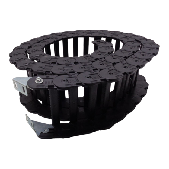
1. Cableveyor Assembly
1-1. Connect any disconnected links and attach the
arms to the hinge side of the link
Caution: Once the disconnected links are connected
and the Cableveyor is installed, determine
which direction the arms will open the easiest
before attaching.
1-2. Fix the locking hook.
Push in the arms from above by hand. Hold the
entire arm down and lightly tap in the locking
hook head from the side with a plastic hammer.
2. Cableveyor Disassembly
2-1. Release the locking hook
Release the locking hook using a screwdriver and
remove the arm from the link.
Use a screwdriver with a 4.5mm or
smaller tip.
Caution: Insert the screwdriver tip and release the locking hook as shown in the following diagram. Facing the
screwdriver in a different direction or forcefully inserting it may result in Cableveyor breakage.
Tsubaki
Cableveyor
Caution: Always wear the appropriate protective gear (safety glasses, gloves, safety shoes,
etc.) when working.
User Manual
®
TKP68H46
(formerly TKP0680)
Link
Locking
hook
1
Arm
Advertisement

Related Manuals for Tsubaki Cableveyor TKP68H46


Summary of Contents for Tsubaki Cableveyor TKP68H46
- Page 1 User Manual Tsubaki ® Cableveyor TKP68H46 (formerly TKP0680) Caution: Always wear the appropriate protective gear (safety glasses, gloves, safety shoes, etc.) when working. 1. Cableveyor Assembly 1-1. Connect any disconnected links and attach the arms to the hinge side of the link...
- Page 2 Dia. 1 Proper removal Lightly push a flat-head screwdriver straight down onto the end of the hook. Confirm that the hook has released and bend the screwdriver backward while pushing forward to remove. Remove the screwdriver and confirm that the hook is securely hidden underneath the arm.
- Page 3 3. Disconnecting the Plastic Bracket 3-1. Find the set mark Screwdriver mark Check that the triangular set mark on the end of the bracket and the screwdriver mark printed on the arm side of the bracket are aligned. Triangular mark 3-2.
- Page 4 4. Cautions When Handling Pretension and sag may appear in the free span depending on the application. However, if selected within Tsubaki’s performance graph then there will be no problems with use. 50mm or over Moving end bracket Fixed end bracket...
Need help?
Do you have a question about the Cableveyor TKP68H46 and is the answer not in the manual?
Questions and answers