Advertisement
Quick Links
North America
Europe
888 Prospect Street, Suite 200
The Black Church, St Mary's Place
La Jolla California 92037
Dublin D07 P4AX, Ireland
+1 424 254 5344
+353 1 254 8222
energizersolar.com
© 2025 Energizer. Energizer and certain graphic designs are trademarks of Energizer Brands, LLC and related subsidiaries and are used under license by 8 Star Energy Pty Ltd.
- 1 -
Australia
Level 35, 477 Collins St, Melbourne
Victoria 3000, Australia
+61 1300 757 827
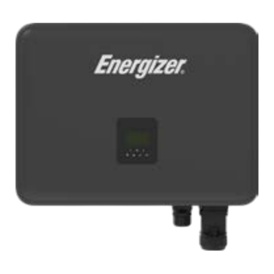
Force HT Plus
Hybrid Inverter
Quick Installation Guide
- 2 -
Advertisement

Summary of Contents for Energizer SOLAR Force HT Plus
- Page 1 +61 1300 757 827 energizersolar.com Quick Installation Guide © 2025 Energizer. Energizer and certain graphic designs are trademarks of Energizer Brands, LLC and related subsidiaries and are used under license by 8 Star Energy Pty Ltd. - 1 - - 2 -...
- Page 2 Packing List Packliste G×1 H×1 I×1 Open the package and take out the product, please check the accessories first. The packing list shown as below. Quick Earth terminal Communication connector Installation Quick installation guide Öffnen Sie die Verpackung und nehmen Sie das Produkt heraus. Biמּe überprüfen Sie zuerst das Zubehör. Die Packliste enthält folgende Artikel: Guide Erdnungsklemme Kommunikationssteckverbinder...
- Page 3 Installation Precaution Space Requirement Vorsichtsmaßnahmen bei der Installation Platzbedarf Make sure the installation site meets the following conditions: Stellen Sie sicher, dass der Installationsort die folgenden Bedingungen erfüllt: Min Distance · Not in areas where highly flammable materials are stored. Mindestabstand Nicht in Bereichen, in denen leicht entflammbare Materialien gelagert werden.
- Page 4 Mounting Steps 08, 50mm Montageschriמּe Drill holes with electric drill, make sure the holes are at least 50mm deep and 8mm wide. Bohren Sie mit einer elektrischen Bohrmaschine Löcher. Stellen Sie sicher, dass die Löcher Fix the bracket on the wall. Choose the place you want to install the inverter. Place the bracket mindestens 50 mm tief und 8 mm breit sind.
- Page 5 Terminals of inverter ≤15° Note: Only authorized personnel are permiמּed to set the connection. Anschlüsse des Wechselrichters Hinweis: Nur autorisiertes Personal darf den Anschluss vornehmen. 2.0 N.m Match the inverter with wall bracket Richten sie den Wechselrichter an der Wandhalterung aus Item / Artikel Item...
- Page 6 Earth Connection Electrical Connection CAUTION The following work is intended for qualified electricians only. ACHTUNG Die folgenden Arbeiten sind nur für Elektrofachkräﬞe bestimmt. Erdungsanschluss Elektrischer Anschluss Note: The baמּery has a standard baמּery cable, please use the standard cable first. Hinweis: Die Baמּerie hat ein Standard-Baמּeriekabel, biמּe verwenden Sie zuerst das Standardkabel.
- Page 7 3. Grid/EPS Connection (3) Installation steps for 5-core wire Installationsschriמּe für 5-adriges Kabel GRID/EPS Anschluss Dimension of stripping line. Dimension of stripping line outside machine. (1) Grid Connection Entfernen sie die Kabel- und Leiterisolierung wie im Bild dargestellt. 16-17mm Netzanschluss 65-72mm H3 Smart series inverters are designed for three-phase grid.
- Page 8 (4) Inserted Eingesteckt Insert the EPS end cable into the EPS end of the rubber core. Aﬞer the cable is in place through the perspective hole, tighten the screw using an S2.5 hexagon wrench with a torque of 2.5±0.1N·m. Führen Sie die Leiterenden des EPS-Kabels auf der EPS-Seite des Steckverbinders entsprechend der Leiterbezeichnung ein. Prüfen Sie die korrekte Position und ziehen Sie die entsprechenden S2.5-Imbusschrauben mit dem Drehmoment von 2,5±0,1Nm an.
- Page 9 Meter connection 3. Meter Connection Diagram Zähleranschluss Messgeräteanschlussdiagramm TO INVERTER-L TO INVERTER-N 1. Export control seמּing: Seמּings On-Grid Parm Export Control xxxxxW ZUM WECHSELRICHTER-L ZUM WECHSELRICHTER-N Exportkontrolleinstellung: Einstellungen Netzgebundene Parm Ausfuhrkontrolle xxxxxW 11 12 2. The electricity meter is connected as follows: So wird der Stromzähler angeschlossen: Legend 11 12...
- Page 10 RJ45 Wiring RJ45 connection RJ45-Verkabelung RJ45-Anschluss 1) Alternate meter connection: The meter RS485 bus cable can be connected via the RJ45 Meter connector: Pin1 = RS485B, Pin2 = RS485A Installation Procedure 1) Alternativer Zähleranschluss: Verbinden sie das RS485-Kabel des Zählers mit der RJ45 Meter-Buchse: Pin1 = RS485B, Pin2 = RS485A Installationsverfahren Insert the network cable into the wire-locking nut, sealing plug and mainbody in turn.
- Page 11 Antenna Connection COM-Connector Wiring Antennenanschluss COM-Stecker-Anschluss Tighten the Antenna's nut by the open-ended wrench with a torque 1.2±0.3N·m. Remove the plug inside the plug and thread the terminal according to the sequence shown in theillustration. Ziehen Sie die Antennenmuמּer mit dem Gabelschlüssel mit einem Drehmoment von 1,2 ± 0,3 Nm fest. Entfernen Sie den Blindstopfen der Kabeleinführung und ziehen Sie das Kommunikationskabel in der gezeigten Reihen- folge in den Stecker ein.
- Page 12 Inverter Start-Up 8. Enter the seמּings page, default password is ‘0000’, select START / STOP and set it to start. (long press “enter” to quickly go to the Inbetriebnahme des Wechselrichters START / STOP page). Rufen Sie die Einstellungsseite im Wechselrichtermenü auf, das Standardkennwort lautet „0000“, wählen Sie START/STOP und stellen Sie es auf Start ein.
- Page 13 Der Wechselrichter kann Restspannungen für bis zu 5 min aufweisen. Apple App Store Google Play Store To connect to the Energizer Solar Application, For more product information, please scan the QR code above please scan the QR codes above. or visit www.energizersolar.com/resources...


Need help?
Do you have a question about the SOLAR Force HT Plus and is the answer not in the manual?
Questions and answers