Advertisement
Quick Links
Advertisement

Related Manuals for Eleiko Prestera Container Rig 4 section


Summary of Contents for Eleiko Prestera Container Rig 4 section
- Page 1 Art.no. 3085879, 3085890, 3085891 Prestera Container Rig 4, 5 & 2 section...
- Page 3 Content Read Before Installation and Use Caution Safety instructions Preventive Maintenance and Inspections Regularly Warranty Product Info Description Footprint area User Guide Required tools General List of components Assembly instructions...
-
Page 4: Warranty
Check tubes and welds for cracks or other defects, replace if necessary. Warranty All products manufactured by ELEIKO are warranted to the original purchaser to be free from defects in workmanship and / or materials under normal use or service as follows:... -
Page 5: Product Info
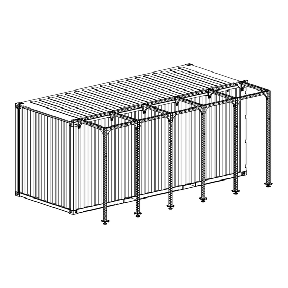
Product Info Description Rig suspension assembled on a container. Prestera Container Rig Prestera Container Rig Prestera Container Rig 20´ 4 section 20´ 5 section 10´ 2 section Product weight Dimensions 6136x3660 - 6136x3660 - 3082x3660 - (L x W x H) 4308x2659 4308x2659 4308x2659... - Page 6 List of Components Container Container Container Rig 20´ Rig 20´ Rig 10´ 4-Section 5 -Section 2 -Section Square tube 70x70x3, L=1046 3085879p26 Square tube 70x70x3, L=1695 3085879p27 Corner left 3085879a3 Corner right 3085879a4 T-Connection Prestera 3085879a2 End Bracket Left, t = 10 3085879a11 End Bracket Right, t = 10 3085879a12...
- Page 7 Bracket Inside Corner Corner Left...
- Page 8 Building 3085879 - 20´ 4 section, 3085890 – 20´ 5 section, 3085891 – 10´ 2 section, proceed to page 14 proceed to page 18 proceed on this page. End Brackets are marked left/right on the surface that is facing the container. Tightening torque 80 Nm / 59 ftlb.
- Page 9 Measure the container and choose the right amount of spacers for your installation. 0 – 30 mm The table below is for reference only. If necessary, adjust the height to get the square tubes parallel to the container.
- Page 10 Insert screws before bracket is mounted to side member. Make sure there is no gap between the tube and the T Connection.
- Page 11 The L-Plate will tighten connection and container together. Choose a suitable hole pattern to get the plate in correct position. M6S M16x120 Tightening torque 80 Nm / 59 ftlb Repeat step 4 and 5 for all T-Connection´s and then proceed to page 22.
- Page 12 End Brackets are marked left/right on the surface that is facing the container. Tightening torque 80 Nm / 59 ftlb Insert screws before bracket is mounted to side member.
- Page 13 Measure the container and choose the right amount of spacers for your installation. 0 – 30 mm The table below is for reference only. If necessary, adjust the height to get the square tubes parallel to the container.
- Page 14 Insert screws before bracket is mounted to side member. Make sure there is no gap between the tube and the T Connection.
- Page 15 The L-Plate will tighten connection and container together. Choose a suitable hole pattern to get the plate in correct position. M6S M16x120 Tightening torque 80 Nm / 59 ftlb Repeat step 4 and 5 for all T-Connection´s and then proceed to page 22.
- Page 16 End Brackets are marked left/right on the surface that is facing the container. Tightening torque 80 Nm / 59 ftlb Insert screws before bracket is mounted to side member.
- Page 17 Measure the container and choose the right amount of spacers for your installation. 0 – 30 mm The table below is for reference only. If necessary, adjust the height to get the square tubes parallel to the container.
- Page 18 Squaretube 70x70x3, L = 1695 Insert screws before bracket is mounted to side member. Make sure there is no gap between the tube and the T Connection.
- Page 19 The L-Plate will tighten connection and container together. Choose a suitable hole pattern to get the plate in correct position. M6S M16x120 Tightening torque 80 Nm / 59 ftlb Repeat step 4 and 5 for all T-Connection´s...
- Page 20 Last steps is the same for all variants. Nut M16 Washer BRB 17x30x3 Slide in Corner Bracket the same distance as opposite side. M6S M16x110 Insert screws before bracket is mounted to side member. M6S M16x120 Torque for M6s M16x110 is set to 80 Nm / 59 ftlb, the rest follows table on page 7.
- Page 21 Components to mount rig on one corner Jointed foot must be screwed in first. Halfway may be adequate. The height of all jointed feet need to be adjusted according to ground level.
- Page 22 Components to mount rig on one middle part Jointed foot must be screwed in first. Halfway may be adequate. The height of all jointed feet need to be adjusted according to ground level.
- Page 24 Eleiko Group AB Klastorpsvägen 18 302 62 Halmstad Sweden +46 35 17 70 00 info@eleiko.com...
Need help?
Do you have a question about the Prestera Container Rig 4 section and is the answer not in the manual?
Questions and answers