Table of Contents
Advertisement
Quick Links
www.ti.com
EVM User's Guide: LMR60410QEVM
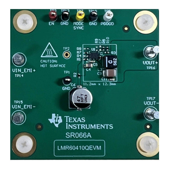
LMR60410-Q1 Evaluation Module
Description
The LMR60410-Q1 is a 36V, 1A, DC/DC buck
converter that features synchronous rectification to
achieve high conversion efficiency in a small footprint.
The EVM operates over a wide input voltage range
of 8V to 36V to provide a regulated 3.3V output
up to 1A load at 2.2MHz switching frequency.
The LMR60410QEVM can support output voltage
regulation accuracy better than 1% and the output
voltage setpoint is adjustable using an external
resistor divider.
Get Started
1. Order the EVM here.
2. Prepare the bench setup per the user's guide
instructions.
3. Power up the EVM by following the recommended
steps.
4. Run tests and measurements. Beware of possible
high component temperatures.
SNVU934 – DECEMBER 2024
Submit Document Feedback
Features
•
Input voltage range: 8V to 36V
•
Output voltage: 3.3V
•
Load current: 0 to 1A
•
Switching frequency: 2.2MHz
•
Adjustable output voltage
•
External synchronization capability
•
Internal spread spectrum capability
•
Selectable pulse-frequency modulation or forced
pulse-width modulation at light load
•
Supports other variants of the IC by replacing
some components
Applications
•
Advanced Driver Assistance Systems (ADAS)
•
Body electronics and lighting
•
Infotainment and cluster
LMR60410QEVM
Copyright © 2024 Texas Instruments Incorporated
Description
LMR60410-Q1 Evaluation Module
1
Advertisement
Table of Contents

Related Manuals for Texas Instruments LMR60410QEVM


Summary of Contents for Texas Instruments LMR60410QEVM
- Page 1 • Adjustable output voltage up to 1A load at 2.2MHz switching frequency. • External synchronization capability The LMR60410QEVM can support output voltage • Internal spread spectrum capability regulation accuracy better than 1% and the output • Selectable pulse-frequency modulation or forced...
-
Page 2: Kit Contents
DC/DC converter capable of delivering up to 4A of load current from an input voltage of 3V up to 36V. The LMR60410QEVM features an output voltage of 3.3V and a switching frequency of 2.2MHz that can support a load up to 4A. -
Page 3: Evm Setup
To measure other waveforms, adjust the oscilloscope as necessary. SNVU934 – DECEMBER 2024 LMR60410-Q1 Evaluation Module Submit Document Feedback Copyright © 2024 Texas Instruments Incorporated... -
Page 4: Quick Start
GND through R8 TP10, TP11 This test point is connected to GND. TP16 VOUT+ Output voltage to EVM. TP17 VOUT– Ground connection for load. LMR60410-Q1 Evaluation Module SNVU934 – DECEMBER 2024 Submit Document Feedback Copyright © 2024 Texas Instruments Incorporated... - Page 5 = 12V = 24V 3.26 = 36V 3.25 0.001 0.002 0.005 0.01 0.02 0.05 0.2 0.3 0.5 Load Current (A) Figure 3-2. Output Voltage Regulation SNVU934 – DECEMBER 2024 LMR60410-Q1 Evaluation Module Submit Document Feedback Copyright © 2024 Texas Instruments Incorporated...
- Page 6 Figure 3-3. Dropout Performance Curves 3.1.2 Load Transients Figure 3-4. Load Transient, I = 0A to 1A Figure 3-5. Load Transient, I = 0.5A to 1A LMR60410-Q1 Evaluation Module SNVU934 – DECEMBER 2024 Submit Document Feedback Copyright © 2024 Texas Instruments Incorporated...
-
Page 7: Startup And Shutdown
Implementation Results 3.1.3 Start-Up and Shutdown Figure 3-6. Start-Up, I = 1A Figure 3-7. Shutdown, I = 1A SNVU934 – DECEMBER 2024 LMR60410-Q1 Evaluation Module Submit Document Feedback Copyright © 2024 Texas Instruments Incorporated... - Page 8 Implementation Results www.ti.com 3.1.4 Hiccup Mode Protection Figure 3-8. Short-Circuit Applied Figure 3-9. Short-Circuit Recovery LMR60410-Q1 Evaluation Module SNVU934 – DECEMBER 2024 Submit Document Feedback Copyright © 2024 Texas Instruments Incorporated...
- Page 9 Implementation Results 3.1.5 Thermal Performance Figure 3-10. Steady State Performance, V = 12V, I = 1A Figure 3-11. Steady State Performance, V = 36V, I SNVU934 – DECEMBER 2024 LMR60410-Q1 Evaluation Module Submit Document Feedback Copyright © 2024 Texas Instruments Incorporated...
- Page 10 Implementation Results www.ti.com 3.1.6 CISPR25 Class 5 Figure 3-12. Steady-State Performance, V = 12V, I = 1A LMR60410-Q1 Evaluation Module SNVU934 – DECEMBER 2024 Submit Document Feedback Copyright © 2024 Texas Instruments Incorporated...
- Page 11 Frequency 400kHz (87.5K) for 4A, but keep 2MHz (15.0K) 5001 TP13 10.0k 5001 MODE/SYNC either connected to RT or GND Figure 4-1. LMR60410QEVM Schematic SNVU934 – DECEMBER 2024 LMR60410-Q1 Evaluation Module Submit Document Feedback Copyright © 2024 Texas Instruments Incorporated...
-
Page 12: Board Layout
Hardware Design Files www.ti.com 4.2 Board Layout Figure 4-2. EVM Top Overlay Figure 4-3. EVM Top Copper Layer Figure 4-4. EVM Mid Layer One LMR60410-Q1 Evaluation Module SNVU934 – DECEMBER 2024 Submit Document Feedback Copyright © 2024 Texas Instruments Incorporated... - Page 13 Hardware Design Files Figure 4-5. EVM Mid Layer Two Figure 4-6. EVM Bottom Copper Layer Figure 4-7. EVM Bottom Overlay SNVU934 – DECEMBER 2024 LMR60410-Q1 Evaluation Module Submit Document Feedback Copyright © 2024 Texas Instruments Incorporated...
- Page 14 3V to 36V Wide-VIN Synchronous Step Down Converter, WQFN- LMR604103SRAKR Texas Instruments CAP, CERM, 22pF, 50V,+/- 5%, C0G/NP0, AEC-Q200 Grade 1, 22pF CGA2B2C0G1H220J050BA 0402 LMR60410-Q1 Evaluation Module SNVU934 – DECEMBER 2024 Submit Document Feedback Copyright © 2024 Texas Instruments Incorporated...
- Page 15 RC0402JR-070RL Yageo America 10.0k RES, 10.0 k, 0.1%, 0.1 W, AEC-Q200 Grade 0, 0402 MCS0402MD1002BE100 Vishay/Beyschlag Test Point, Miniature, Red, TH 5000 Keystone Electronics SNVU934 – DECEMBER 2024 LMR60410-Q1 Evaluation Module Submit Document Feedback Copyright © 2024 Texas Instruments Incorporated...
-
Page 16: Additional Information
Additional Information www.ti.com 5 Additional Information 5.1 Trademarks All trademarks are the property of their respective owners. LMR60410-Q1 Evaluation Module SNVU934 – DECEMBER 2024 Submit Document Feedback Copyright © 2024 Texas Instruments Incorporated... - Page 17 STANDARD TERMS FOR EVALUATION MODULES Delivery: TI delivers TI evaluation boards, kits, or modules, including any accompanying demonstration software, components, and/or documentation which may be provided together or separately (collectively, an “EVM” or “EVMs”) to the User (“User”) in accordance with the terms set forth herein.
- Page 18 www.ti.com Regulatory Notices: 3.1 United States 3.1.1 Notice applicable to EVMs not FCC-Approved: FCC NOTICE: This kit is designed to allow product developers to evaluate electronic components, circuitry, or software associated with the kit to determine whether to incorporate such items in a finished product and software developers to write software applications for use with the end product.
- Page 19 www.ti.com Concernant les EVMs avec antennes détachables Conformément à la réglementation d'Industrie Canada, le présent émetteur radio peut fonctionner avec une antenne d'un type et d'un gain maximal (ou inférieur) approuvé pour l'émetteur par Industrie Canada. Dans le but de réduire les risques de brouillage radioélectrique à...
- Page 20 www.ti.com EVM Use Restrictions and Warnings: 4.1 EVMS ARE NOT FOR USE IN FUNCTIONAL SAFETY AND/OR SAFETY CRITICAL EVALUATIONS, INCLUDING BUT NOT LIMITED TO EVALUATIONS OF LIFE SUPPORT APPLICATIONS. 4.2 User must read and apply the user guide and other available documentation provided by TI regarding the EVM prior to handling or using the EVM, including without limitation any warning or restriction notices.
- Page 21 Notwithstanding the foregoing, any judgment may be enforced in any United States or foreign court, and TI may seek injunctive relief in any United States or foreign court. Mailing Address: Texas Instruments, Post Office Box 655303, Dallas, Texas 75265 Copyright © 2023, Texas Instruments Incorporated...
-
Page 22: Important Notice
TI products. TI’s provision of these resources does not expand or otherwise alter TI’s applicable warranties or warranty disclaimers for TI products. TI objects to and rejects any additional or different terms you may have proposed. IMPORTANT NOTICE Mailing Address: Texas Instruments, Post Office Box 655303, Dallas, Texas 75265 Copyright © 2024, Texas Instruments Incorporated...
Need help?
Do you have a question about the LMR60410QEVM and is the answer not in the manual?
Questions and answers