
Related Manuals for Metal Man MP251ILCD


Summary of Contents for Metal Man MP251ILCD
- Page 1 MP251ILCD OWNER’S MANUAL 7/2022 WARNING: Read carefully and understand all ASSEMBLY AND OPERATION INSTRUCTIONS before operating. Failure to follow the safety rules and other basic safety precautions may result in serious personal injury.
- Page 2 90 days Parts for Metal Man Work Gear welding carts and welding cabinets. This warranty covers the absence of or defective parts. 3 year This 3 year warranty covers parts and Labor on items such as: transformer, reactor, rectifier, solenoid valve, PC Board, switches, controls, gas valve, drive motor, drive system other than drive roll and any other component that requires the removal of the sheet metal to access.
- Page 3 GENERAL SAFETY RULES WARNING: Read and understand all instructions. Failure to follow all instructions listed below may result in serious injury. CAUTION: Do not allow persons to operate or assemble this MMP251ILCD until they have read this manual and have developed a thorough understanding of how the MIG/Stick 220Si works.
- Page 4 1.3 Use of Your Welder Do not operate the welder if the output cable, electrode, torch, wire or wire feed system is wet. Do not immerse them in water. These components and the welder must be completely dry before attempting to use them. -Follow the instructions in this manual.
- Page 5 -Do not weld on coated materials (galvanized, cadmium plated or containing zinc, mercury or barium). They will emit harmful fumes that are dangerous to breathe. If necessary, use a ventilator, respirator with air supply or remove the coating from the material in the weld area. -The fumes emitted from some metals when heated are extremely toxic.
- Page 6 Sparks/Flying Debris Welding creates hot sparks that can cause injury. Chipping slag off welds creates flying debris. -Always wear protective apparel: ANSI-approved safety glasses or shield, welder’s hat and ear plugs to keep sparks out of ears and hair. Electromagnetic Field -Electromagnetic fields can interfere with various electrical and electronic devices such as pacemakers.
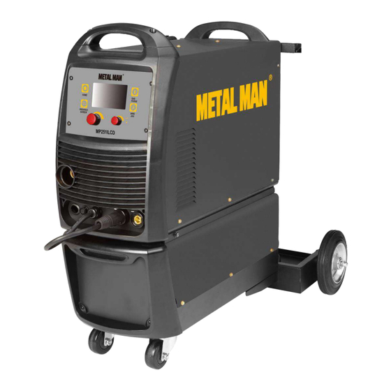
- Page 7 115 lb. DESCRIPTION The Metal Man MMP251ILCD is an inverter-powered, wire feed welder for flux core and MIG welding plus a DC stick welder. It features a Synergic LCD control that allows the operator to select process and weld settings. It comes complete with two regulators and gas hoses for easy connection for MIG welding plus with optional purchase a weld cable and electrode holder for DC stick welding.
- Page 8 MIG TORCH The welding wire is driven through the welding cable and torch to the work piece. It is attached to the drive system. The trigger activates the drive motor. POWER CORD AND PLUG Plug this unit into a 230V, 50-amp circuit breaker power supply when operating on 230V. INERT GAS REGULATOR’S AND GAS HOSE The Inert Gas Regulator installs on the shielding gas cylinder for MIG welding with solid wires.
- Page 9 INSTALLATION 1. POWER REQUIREMENT - AC single phase 230V (200-240V) 60 HZ fused with a 50-amp time delayed fuse or circuit breaker is required. DO NOT OPERATE THIS UNIT if the ACTUAL power source voltage is less than 215 volts AC or greater than 240 volts AC. Electrical Shock •...
- Page 10 3.3 If there is wire already installed in the welder, roll it back onto the wire spool by hand-turning the spool clockwise. Be careful not to all the wire to come out of the rear end of the inlet guide tube without holding onto it or the wire spool will unspool itself. Put the end of the wire into the hole on the outside edge of the wire spool and bend it over to hold the wire in place.
- Page 11 The welding wire should always come off the bottom of the spool into the drive mechanism. See following figure. 4.2.5 The welder can use either 8 inch or 11-inch spools. The wire spool retainer secures the spool of wire onto the spool hub. The Wire Spool Tension Set Screw controls the tension on the spool.
- Page 12 -Make certain that the welding wire is actually going into the torch liner. If not, the wire will jam up in the mechanism. 4.2.11 Line the wire up with the correct groove in the drive roller. Place the drive tension arm back above the drive roller.
- Page 13 • Use the proper regulators, gas hose and fittings for the specific application. 6.1 Polarity Changing - When MIG wire is used, shielding gas is required and the polarity on this unit needs to be electrode positive. 6.1.1 Electrode Positive for MIG Welding - The Weld Power Cable should be connected to the positive (+) weld output connection on the front of the machine.
- Page 14 Reference Subassembly Gas Bottle Valve Gas Flow Gauge (Set at 20 CFH) Gas Pressure Gauge Regulator Gas Flow Adjuster Gas Hose Connection Gas Cylinder 6.5 Open the Gas Bottle Valve on the cylinder of gas. 6.6 Turn the Gas Flow Adjuster on the regulator so that the gas flow rate is set at approximately 20 CFH.
- Page 15 ASSEMBLY 1. MIG TORCH ASSEMBLY 1.1 Locate the retaining bolt inside the front panel on the drive system. Loosen the retaining bolt. 1.2 Make note of the retaining groove on the back end of the MIG torch. Retaining Groove Retaining Bolt 1.3 Insert the back end of the MIG torch into the MIG socket on the front of your machine.
- Page 16 2.4 Open the wire compartment door. Spool Gun Weld Power Connection 2.5 Connect the weld power connection to the bolt on the side of the MIG connector. 2.6 Connect the Spool Gun 5-Pin trigger connector to the Spool Gun 5-Pin receptacle on the front of the machine.
- Page 17 OPERATING INSTRUCTIONS • High voltage danger from power source! Consult a qualified electrician for proper installation of receptacle. This welder must be grounded while in use to protect the operator from electrical shock. • Do not remove grounding prong or alter the plug in any way. Use only the supplied adapter between the plasma cutter's power cord and the power source receptacle.
- Page 18 GENERAL SYSTEM SET-UP 1. Press the ENTER BUTTON. 2. Turn the MULTI-FUNCTION ADJUSTMENT/SELECTION KNOB to the SETTING selection. 3. Push in the MULTI-FUNCTION ADJUSTMENT/SELECTION KNOB. 4. Language a. Press the MULTI-FUNCTION ADJUSTMENT/SELECTION KNOB to change the orange outline to solid orange background. b.
- Page 19 a. Turn the MULTI-FUNCTION ADJUSTMENT/SELECTION KNOB until BRIGHTNESS screen is displayed. b. Push in the MULTI-FUNCTION ADJUSTMENT/SELECTION KNOB so the brightness setting has an orange background. c. Turn the MULTI-FUNCTION ADJUSTMENT/SELECTION KNOB to selected desired screen brightness. d. Push in the MULTI-FUNCTION ADJUSTMENT/SELECTION KNOB to select. 7.
- Page 20 WIRE WELDING SET-UP 1. Press the ENTER BUTTON. 2. Turn the MULTI-FUNCTION ADJUSTMENT/SELECTION KNOB to the SETTING selection you need. Press in the MULTI-FUNCTION ADJUSTMENT/SELECTION KNOB to make your selection. a. MIG Steel i. Choose what shielding gas you will be using b.
- Page 21 NOTE: WELDING ALUMINUM WITH THE MIG GUN CAN BE DIFFICULT. We always suggest the use of a spool gun to avoid feeding problems associated with a soft aluminum wire. d. MIG CuSi (Copper/Silicon Alloy) e. Manual MIG 3. Follow the on-screen display that shows the weld cable connections a.
- Page 22 c. For MIG Stainless, MIG Al, Manual MIG – Connect the WELD POWER CABLE to the Positive (+) weld output connection. Then the ground cable to the Negative (+) weld output connection. NOTE: WHEN USING A SPOOL GUN FOR ALUMINUM follow the Spool Gun Assembly instructions. 4.
- Page 23 7. Your Welder is now ready to weld! 8. Fine Tuning Parameters – The set-up process is designed to get the welder set up into a good welding condition for the material you are welding. You may choose to adjust the parameters to meet your individual weld need.
- Page 24 a. 2T – No Trigger Hold. Pull and hold the trigger to weld. Release the trigger to stop welding. b. 4T – Trigger Hold. Pull and release the trigger once to start the arc, then once again to end the arc. The Trigger Hold allows operators flexibility to not have to hold the trigger during long welds.
- Page 25 d. Press the MULTI-FUNCTION ADJUSTMENT/SELECTION KNOB to confirm. 14. Run In WFS – Run In WFS allows you to adjust the speed of the wire feeding; after you pull the trigger and just prior to a weld establishing. Wire that “Runs In” slower will generally provide a smoother and less “Poppy”...
- Page 26 STICK WELDING SET-UP 1. Press the ENTER BUTTON. 2. Turn the MULTI-FUNCTION ADJUSTMENT/SELECTION KNOB until the Stick/MMA screen is displayed. 3. Push in the MULTI-FUNCTION ADJUSTMENT/SELECTION KNOB to confirm your selection. 4. Follow the display set-up: a. Connect the Electrode Holder to the Positive (+) Weld Output Connection. b.
- Page 27 a. When the Amperage is highlighted in Orange, you are able to turn the MULTI-FUNCTION ADJUSTMENT/SELECTION KNOB to increase or decrease amperage. 6. Push in the MULTI-FUNCTION ADJUSTMENT/SELECTION KNOB to change the orange background to an orange outline. 7. Turn the MULTI-FUNCTION ADJUSTMENT/SELECTION KNOB to Hot Start. 8.
- Page 28 will provide a very short boost of output amperage when the arc is too short. Turn the MULTI-FUNCTION ADJUSTMENT/SELECTION KNOB to the desired Arc Force Setting. b. Press the MULTI-FUNCTION ADJUSTMENT/SELECTION KNOB to confirm your selection 13. Turn the MULTI-FUNCTION ADJUSTMENT/SELECTION KNOB to VRD. 14.
- Page 29 Turn the MULTI-FUNCTION ADJUSTMENT/SELECTION KNOB to increase or decrease amperage. NOTE: This unit is automatically in the LIFT TIG setting. This unit does not have the remote-control facilities or the HF requirement necessary to perform HF starts with a foot pedal. MIG OPERATION 1.
- Page 30 e. Connect the Ground Clamp to a scrap piece of the same type of material which you will be welding. It should be equal to or greater than the thickness of the actual work piece, and free of oil, paint, rust, etc. f.
- Page 31 Travel speed is the rate at which the torch is being pushed or pulled along the weld joint. For a fixed heat setting, the faster the travel speed, the lower the penetration and the lower and narrower the finished weld bead. Likewise, the slower the travel speed, the deeper the penetration and the higher and wider the finished weld bead will be.
- Page 32 VERTICAL POSITION it is easier for many people to pull the torch from top to bottom. It can be difficult to prevent the puddle from running downward. Pushing the torch from bottom to top may provide better puddle control and allow slower rates of travel speed to achieve deeper penetration.
- Page 33 NOTE: WHEN USING SELF-SHIELDING FLUX-CORE WIRE it is very important to thoroughly chip and brush the slag off each completed weld bead before making another pass or the next pass will be of poor quality. Fillet Weld Joints. Most fillet weld joints, on metals of moderate to heavy thickness, will require multiple pass welds to produce strong joint.
- Page 34 are 0.035-inch self-shielding flux-core wire. Do not use 0.030-inch self-shielding flux core wires when using the burn-through method unless the metal is VERY thin or excessive filler metal build-up and minimal penetration is acceptable. Always select the HIGH heat setting with the burn-through method and tune in the wire speed prior to making a spot weld.
- Page 35 the correct bevel should be around 60 degrees. See the following illustration: Based on different welding positions, there are different welding joints. See the following illustration for more information. 2. GROUND CLAMP CONNECTION Clear any dirt, rust, scale, oil, or paint on the ground clamp. Make certain you have a good solid ground connection.
- Page 36 4. SELECTING THE PROPER ELECTRODE There is no golden rule that determines the exact rod or heat setting required for every situation. The type and thickness of metal and the position of the work piece determine the electrode type and the amount of heat needed in the welding process. Heavier and thicker metals require more amperage.
- Page 37 Holding the electrode The best way to grip the electrode holder is the way that feels most comfortable to you. Position the electrode to the work piece when striking the initial arc, it may be necessary to hold the electrode perpendicular to the work piece. Once the arc is started the angle of the electrode in relation to the work piece should be between 10 and 30 degrees.
- Page 38 c. Types of weld bead The following paragraphs discuss the most commonly used arc welding beads. The stringer bead is formed by traveling with the electrode in a straight line while keeping the electrode centered over the weld joint. Stringer Bead Weave Bead The weave bead is used when you want to deposit metal over a wider space than would be possible with a stringer bead.
- Page 39 seam. Moving the electrode rapidly or erratically will prevent proper fusion or create a lumpy, uneven bead. f. Finish the bead As the coating on the outside of the electrode burns off, it forms an envelope of protective gases around the weld. This prevents air from reaching the molten metal and creating an undesirable chemical reaction.
- Page 40 6. Turn on the input power switch on the welder. 7. Turn on the regulator on the bottle of shielding gas and adjust the regulator to approximately 20 CFH. Then open the shielding gas valve on the torch to start the flow of shielding gas. 8.
- Page 41 TROUBLESHOOTING Failure Possible Cause Corrective Action Unit is not plugged in. Plug in unit. Unit Does Not Input power circuit breaker is not on. Reset input power circuit breaker. Power Up. The main power switch is not working. Replace main power switch. Leave power on and let the fan cool the The internal temperature is too high.
- Page 42 Failure Possible Cause Corrective Action Torch liner is plugged. Clear or replace torch liner. Connect shielding gas supply and turn No shielding gas. shielding gas on. Remove and reconnect the MIG torch to MIG torch is not correctly installed and make certain it is completely installed into shielding gas is not transferring to the arc.
- Page 43 DIAGRAM Page of 46...
- Page 44 PARTS LIST Reference Part Number Part Description Quantity TORCH SELECTION SWITCH 105200327 MALE GAS QUICK CONNECT 105200328 FEMALE GAS QUICK CONNECT 105200052 Control PCB 105200292 Main PCB 105200293 Main PCB Support Bracket 105200294 Reactor 105200295 Handle 105200296 Plastic Front Bezel 105200297 LCD Control PCB 105200298...
- Page 45 DIAGRAM PARTS LIST Reference Part Number Part Description Quantity 105200482 CONNECTING BAR 105200483 CART ENCLOSURE 105200484 CART BACK PANEL 105200485 DRAWER SLIDING RAIL 105200122 CART BACK WHEEL 155200079 CYLINDER RACK 105200486 CART DRAWER 105200487 CART BOTTOM 105200488 ACCESSORIES BIN 105200128 CASTER WHEEL 105200489 CART FRONT BEZEL...
- Page 46 METAL MAN WORK GEAR CO. 1760 Prospect Ct, Suite 120 Appleton, WI 54914 888-762-4045 www.metalmangear.com Made in China Page of 46...
Need help?
Do you have a question about the MP251ILCD and is the answer not in the manual?
Questions and answers