Table of Contents
Advertisement
Quick Links
Advertisement
Table of Contents

Related Manuals for Metal Man 200iDV


Summary of Contents for Metal Man 200iDV
- Page 1 Inver ter Powered 200iDV AC/DC TIG OWNER’S MANUAL 04/2018 WARNING: Read carefully and understand all ASSEMBLY AND OPERATION INSTRUCTIONS before operating. Failure to follow the safety rules and other basic safety precautions may result in serious personal injury.
-
Page 2: Limited Warranty
Limited to the warranty periods below, Metal Man Work Gear Co will repair or replace the item under warranty that fails due to defects in material and workmanship. Metal Man Work Gear must be notified within 30 days of the failure, so as to provide instructions on how to proceed with the repair of your welder and warranty claim processing. -
Page 3: General Safety Rules
GENERAL SAFETY RULES WARNING: Read and understand all instructions. Failure to follow all instructions listed below may result in serious injury. CAUTION: Do not allow persons to operate or assemble this Flux Core 125 until they have read this manual and have developed a thorough understanding of how the Flux Core 125 works. - Page 4 -Do not allow any body part to come in contact with the welding wire if you are in contact with the material being welded, ground or electrode from another welder. -Do not weld if you are in an awkward position. Always have a secure stance while welding to prevent accidents.
- Page 5 your eyes and skin. Do not look at the welding arc without proper eye protection. -Always use a helmet that covers your full face from the neck to top of head and to the back of each ear. -Use a lens that meets ANSI standards and safety glasses. For welders under 160 Amps output, use a shade 10 lens;...
- Page 6 Electromagnetic Field -Electromagnetic fields can interfere with various electrical and electronic devices such as pacemakers. -Consult your doctor before using any electric arc welder or cutting device -Keep people with pacemakers away from your welding area when welding. -Do not wrap cable around your body while welding. -Wrap MIG gun and ground cable together whenever possible.
-
Page 7: Technical Specifications
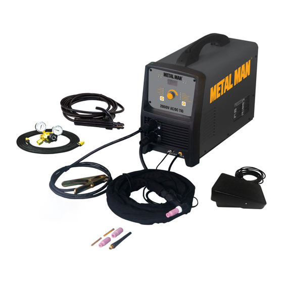
The 200iDV AC/DC TIG is the ideal Stick and TIG welder for every shop. The DC stick mode allows you to stick weld when your application requires it. In the DC TIG mode you are able to TIG weld metals such as steel and stainless steel. - Page 8 Indicator Digital Functional Lights Meters Control Weld Process Indicators Electrode Holder And Weld Cable Regulator/Flowgauge With Gas Hose Weld Parameter Setting Indicators Electrode Holder Remote Foot TIG Torch And Cable Pedal Control GROUND CABLE AND CLAMP The ground cable and clamp are attached to the work piece to complete the circuit allowing the flow of current needed to weld.
- Page 9 ASSEMBLY Electrical Shock Can Kill! High voltage danger from power source! Consult a qualified electrician for proper installation of receptacle. This welder must be grounded while in use to protect the operator from electrical shock. Do not remove grounding prong or alter the plug in any way. Use only the supplied adapter between the welder's power cord and the power source receptacle.
-
Page 10: Back Panel Connections
5. TIG WELDING CONNECTION – DC TIG welding is generally performed DC Electrode negative. That means that the TIG torch and cable would be attached to the Negative (-) weld output connection and the ground cable and clamp would be attached to the Positive (+) weld output connection. Use this same connection when AC TIG welding. -
Page 11: Gas Installation
GAS INSTALLATION Shielding gas cylinders and high pressure cylinders can explode if damaged, so treat them carefully. Never expose cylinders to high heat, sparks, open flames, mechanical shocks or arcs. Do not weld on the cylinder. Always secure cylinder upright to a cart or stationary object. ... -
Page 12: Remote Control Installation
heard when the remote is activated. No gas flow will result in a harsh arc. Gas selection: Except for very specialized TIG welding applications, TIG welding can be done with 100% Argon. Consult your gas supplier for more information. 8. REMOTE CONTROL INSTALLATION NOTE: When stick welding, remove all remote controls. -
Page 13: Process Selection
1. PROCESS SELECTION AVOID ACCIDENTAL ARCING When in the STICK welding mode, the weld output connections of this unit are electrically hot. To avoid accidental arcing, be mindful of the welding accessories that are connected to the weld output connections. ... - Page 14 Weld Parameter Indicator Lights Weld Process Indicator Lights Push to Sequence Through Weld Processes Weld Parameter Adjustment a. See the ASSEMBLY section for the correct welding accessories connections for DC Stick Welding. b. Turn the input power switch ON. c. Press the button below the weld process indicators until the weld process indicator light next to DC Stick is on.
- Page 15 Weld Parameter Indicator Lights Weld Process Indicator Lights Push to Sequence Through Weld Processes Weld Parameter Adjustment f. Turn the Parameter Adjustment Control until the Digital Meter displays the desired Current (A) setting. This is the current setting that the operator wants when the foot pedal is completely pressed to the maximum.
- Page 16 4. AC TIG SET-UP a. See the ASSEMBLY section for the correct welding accessory connections for AC TIG Welding. Turn the input power switch ON. Press the Weld Process Selector button until the Weld Process Indicator Light next to AC TIG is on. If the operator wants to use Pulse AC TIG, press the Weld Process Selector until the Weld Process Indicator Light next to Pulse AC TIG is on.
- Page 17 maximum setting by varying the amount the operator is pressing down on the foot pedal. If the operator is using Pulse AC TIG, this setting will be the maximum peak amperage, or the amperage that the welder will pulse up to when the foot pedal is completely pressed to the maximum.
-
Page 18: Setting Up The Work Piece
DC STICK OPERATION • High voltage danger from power source! Consult a qualified electrician for proper installation of receptacle. This cutter must be Grounded while in use to protect the operator from electrical shock. • Do not remove grounding prong or alter the plug in any way. Use only the supplied adapter between the welder's power cord and the power source receptacle. -
Page 19: Ground Clamp Connection
2. GROUND CLAMP CONNECTION Clear any dirt, rust, scale, oil or paint on the ground clamp. Make certain you have a good solid ground connection. A poor connection at the ground clamp will waste power and heat. Make sure the ground clamp touches the metal. 3. -
Page 20: Welding Techniques
4.1. When proper rod is used: 4.1.a. The bead will lay smoothly over the work without ragged edges 4.1.b. The base metal puddle will be as deep as the bead that rises above it 4.1.c. The welding operation will make a crackling sound similar to the sound of eggs frying 4.2. - Page 21 work piece should be between 10 and 30 degrees. This will allow for good penetration, with minimal spatter. 6.2 Striking the arc EXPOSURE TO A WELDING ARC IS EXTREMELY HARMFUL TO THE EYES AND SKIN! Prolonged exposure to the welding arc can cause blindness and burns. Never strike an arc or begin welding until you are adequately protected.
- Page 22 The weave bead: Used when you want to deposit metal over a wider space than would be possible with a stringer bead. It is made by weaving from side to side while moving with the electrode. It is best to hesitate momentarily at each side before weaving back the other way. 6.4 Welding position Flat position: It is easiest of the welding positions and is most commonly used.
- Page 23 accumulation of dirty metal scale on the finished weld. Slag should be removed by using a chipping hammer. PEENING THE SLAG FROM A WELD JOINT CAUSES SMALL CHIPS OF METAL TO FLY THROUGH THE AIR! Metallic chips flying through the air can cause eye injury or injury to other parts of the head, hands or exposed portions of the body.
- Page 24 BASIC TIG WELDING OPERATION High voltage danger from power source! Consult a qualified electrician for proper installation of receptacle at the power source. This welder must be grounded while in use to protect the operator from electrical shock. If you are not sure if your outlet is properly grounded, have it checked by a qualified electrician.
- Page 25 Guide for Selecting F iller W ire Diameter Tungsten Electrode T ypes Aluminum W elding Material W elding Rate Page of 33...
- Page 26 TIG W elding is generally regarded as a sp ecialized p rocess tha t requires operato r competenc y. W hile many of the p rinciples outlined in th e pre vious Arc W elding section a re a pplicable a comprehensive outline of the TIG W elding process is outside th e scope of this O pe ra ting Manual .
-
Page 27: Maintenance
MAINTENANCE • High voltage danger from power source! Consult a qualified electrician for proper installation of receptacle. This cutter must be Grounded while in use to protect the operator from electrical shock. • Do not remove grounding prong or alter the plug in any way. Use only the supplied adapter between the plasma cutter's power cord and the power source receptacle. -
Page 28: Troubleshooting
TROUBLESHOOTING Failure Possible Cause Corrective Action Unit is not plugged in. Plug in unit. Unit does not power Input power circuit breaker is not on. Reset input power circuit breaker. The main power switch is not working. Replace main power switch. Leave power on and let the fan cool the unit. - Page 29 MAIN CIRCUIT CHART Page of 33...
-
Page 30: Diagram & Parts List
DIAGRAM & PARTS LIST Page of 33... - Page 31 GAS CONNECTOR 105200131 REMOTE CONTROL CONNECTOR 105200136 WELD OUTPUT QUICK CONNECTOR 105500131 POTENTIOMETER KNOB 105500132 FRONT PANEL 145500002 FRONT PANEL DECAL 200iDV AC/DC 105500113 FRONT PANEL PC BOARD 145500003 PLASTIC FRONT BEZEL 105500133 HALL 105500115 INDUCTOR 105500116 HF PCB MOUNTING BRACKET...
- Page 32 Reference # Part# Description Qty. 105500012 NOZZLE #5 105500013 NOZZLE#6 105500014 NOZZLE#7 105500078 COLLET BODY 105500010 COLLET 105500079 TORCH HEAD 105500080 SHORT BACK CAP 105500081 LONG BACK CAP 105500082 CONNECTOR ASSEMBLY 105500083 TIG TORCH HANDLE 105500084 TIG TORCH GAS HOSE 105500085 TIG TORCH CONTROL CABLE 105500086...
- Page 33 Metal Man Work Gear Company 1760 Prospect Ct #120 Appleton, WI 54914 w w w . m e t a l m a n g e a r . c o m 8 8 8 - 7 6 2 - 4 0 4 5...
Need help?
Do you have a question about the 200iDV and is the answer not in the manual?
Questions and answers