Table of Contents
Advertisement
Quick Links
Advertisement
Table of Contents

Related Manuals for Metal Man FC135T


Summary of Contents for Metal Man FC135T
- Page 1 FC135T OWNER’S MANUAL 03/2018 WARNING: Read carefully and understand all ASSEMBLY AND OPERATION INSTRUCTIONS before operating. Failure to follow the safety rules and other basic safety precautions may result in serious personal injury. www.MetalManGear.com Toll Free Help 888-762-4045...
-
Page 2: Warranty
Limited to the warranty periods below, Metal Man Work Gear Co will repair or replace the item under warranty that fails due t o defects in material and workmanship. Metal Man Work Gear must be notified within 30 days of the failure, so as to provide instructions on how to proceed with the repair of your welder and warranty claim processing. -
Page 3: General Safety Rules
GENERAL SAFETY RULES WARNING: Read and understand all instructions. Failure to follow all instructions listed below may result in serious injury. CAUTION: Do not allow persons to operate or assemble this unit until they have read this manual and have developed a thorough understanding of how this unit works. WARNING: The warnings, cautions, and instructions discussed in this instruction manual cannot cover all possible conditions or situations that could occur. - Page 4 material being welded, ground or electrode from another welder. -Do not weld if you are in an awkward position. Always have a secure stance while welding to prevent accidents. Wear a safety harness if working above ground. -Do not drape cables over or around your body. -Wear a full coverage helmet with appropriate shade (see ANSI Z87.1 safety standard) and safety glasses while welding.
- Page 5 -Always use a helmet that covers your full face from the neck to top of head and to the back of each ear. -Use a lens that meets ANSI standards and safety glasses. For welders under 160 Amps output, use a shade 10 lens; for above 160 Amps, use a shade 12. Refer to the ANSI standard Z87.1 for more information.
-
Page 6: Technical Specifications
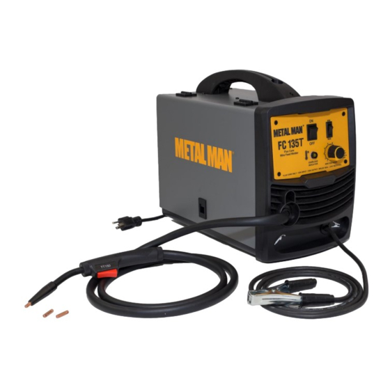
Electromagnetic Field -Electromagnetic fields can interfere with various electrical and electronic devices such as pacemakers. -Consult your doctor before using any electric arc welder or cutting device -Keep people with pacemakers away from your welding area when welding. -Do not wrap cable around your body while welding. -Wrap MIG gun and ground cable together whenever possible. - Page 7 DESCRIPTION METAL MAN FC135T 115 volt input, 135 amp AC output flux core only wire feed welders is economical and easy to use. It requires no shielding gas and welds 8 gauge to 3/16" mild steel materials with .030" or .035" flux core wires on 4" or 8" spools. This unit features 2 voltage ranges, a set up chart, a cooling fan, trigger activated arc, overload protection, 8-1/2 ft torch with Tweco style series 11 replacement parts and 6 ft ground cable and clamp.
-
Page 8: Installation
Welding Cable and Torch The welding wire is driven through the welding cable and torch to the work piece. It is attached to the drive system; the gun trigger activates the drive motor. Thermal Indicator If the duty cycle of the welder is exceeded the internal temperature will exceed safe temperatures and the machine will shut down. - Page 9 3. INSTALL THE WIRE ROLLER - The wire roller has been factory installed. However, check to make certain the correct wire groove is in place to accommodate the size of wire you are using. Open the wire feed compartment. Adjust the drive roller according to the following steps, see following picture about the wire feeder structure: a.
- Page 10 b. Installing the wire Electrical Shock • Electric shock can cause injury or death! Always turn the POWER switch OFF and unplug the power cord from the AC power source before installing wire. NOTE: - Before installing, make sure that you have removed any old wire from the torch assembly. This will help to prevent the possibility of the wire jamming inside the gun liner.
- Page 11 8 Inch 4 Inch g. The welder can use either 4 inch or 8 inch spools. See the following figure for additional reference. The wing nut controls the tension on the spool. h. Setting the wire spool tension. a) Turn the spool of wire with one hand. b) Increase the spool tension by tightening (turn clockwise) the wing nut while turning the spool.
- Page 12 p. NOW YOU CAN LET GO OF THE WIRE. q. Plug in the welder power cord and turn the welder ON. Set the Voltage switch to the voltage setting recommended for the gauge metal that is to be welded. Refer to the set-up chart on the back side of the drive compartment door.
-
Page 13: Operation
OPERATION • High voltage danger from power source! Consult a qualified electrician for proper installation of receptacle. This cutter must be grounded while in use to protect the operator from electrical shock. • Do not remove grounding prong or alter the plug in any way. Use only the supplied adapter between the welder's power cord and the power source receptacle. - Page 14 6. DISTANCE FROM THE WORK PIECE - If the nozzle is held off the work piece, the distance between the nozzle and the work piece should be kept constant and should not exceed 1/4 inch or the arc may begin sputtering, signaling a loss in welding performance. 7.
- Page 15 ELECTRIC SHOCK CAN CAUSE INJURY OR DEATH! To prevent ELECTRIC SHOCK, do not perform any welding while standing, kneeling, or lying directly on the grounded work piece. 8.1 Moving the torch Torch travel refers to the movement of the torch along the weld joint and is broken into two elements: Direction and Speed.
- Page 16 8.3 Welding position FLAT POSITION is easiest of the welding positions and is most commonly used. It is best if you can weld in the flat position if at all possible as good results are easier to achieve. HORIZONTAL POSITION is performed very similarly to the flat weld except that angle B (see HOLDING THE TORCH) is such that the wire, directed more toward the metal above the weld joint is to help prevent the weld puddle from running downward while still allowing slow enough travel speed.
- Page 17 falling into the nozzle. Angle B should be held at zero degrees so that the wire is aiming directly into the weld joint. If you experience excessive dripping of the weld puddle, select a lower heat setting. Also, the weave bead tends to work better than the stringer. 8.4 Multiple pass welding Butt Weld Joints: When butt welding thicker materials, you will need to prepare the edges of the material to be joined by grinding a bevel on the edge of one or both pieces of the metal being joined.
- Page 18 8.5 Spot welding There are three methods of spot welding: Burn-Through, Punch and Fill, and Lap. Each has advantages and disadvantages depending on the specific application as well as personal preference. 1. The BURN-THROUGH METHOD welds two overlapped pieces of metal together by burning through the top piece and into the bottom piece.
-
Page 19: Maintenance
8.6 SPOT WELDING INSTRUCTIONS 1. Select the wire diameter and heat setting recommended above for the method of spot welding you intend to use. 2. Tune in the wire speed as if you were going to make a continuous weld. 3. -
Page 20: Electrical Diagram
ELECTRICAL DIAGRAM Page of 24... -
Page 21: Diagram & Parts List
DIAGRAM & PARTS LIST Page of 24... - Page 22 Reference # Part# Description Qty. 145200013 DOOR 145200017 FC135T SET-UP GUIDE 105200040 DOOR LATCH 145200014 FRONT PLASTIC BEZEL 145200016 FRONT PANEL DECAL FC135T 105200410 POWER SWITCH 105200411 VOLTAGE SWITCH 105200036 OVERLOAD INDICATOR 105200412 POTENTIOMETER KNOB 105200032 TORCH 105200413 TORCH STRAIN RELIEF...
- Page 23 Reference # Part# Description Qty. 105200034 FLUX CORE NOZZLE 105200043 .030 CONTACT TIP 105200033 CONTACT TIP ADAPTER 105200104 TORCH INSULATOR 105200105 TORCH LINER 105200106 TORCH HEAD TUBE For replacement parts and technical questions contact the technical help line at 1-888-762-4045 Page of 24...
- Page 24 METAL MAN WORK GEAR CO. 1760 Prospect Ct, Suite 120 Appleton, WI 54914 888-762-4045 www.metalmangear.com Made in China Page of 24...
Need help?
Do you have a question about the FC135T and is the answer not in the manual?
Questions and answers