Table of Contents
Advertisement
Quick Links
Advertisement
Table of Contents

Related Manuals for Metal Man FC130i


Summary of Contents for Metal Man FC130i
- Page 1 FC130i OWNER’S MANUAL 05/2019 WARNING: Read carefully and understand all ASSEMBLY AND OPERATION INSTRUCTIONS before operating. Failure to follow the safety rules and other basic safety precautions may result in serious personal injury. www.MetalManGear.com Toll Free Help 888-762-4045...
-
Page 2: Warranty
Limited to the warranty periods below, Metal Man Work Gear Co will repair or replace the item under warranty that fails due t o defects in material and workmanship. Metal Man Work Gear must be notified within 30 days of the failure, so as to provide instructions on how to proceed with the repair of your welder and warranty claim processing. -
Page 3: General Safety Rules
GENERAL SAFETY RULES WARNING: Read and understand all instructions. Failure to follow all instructions listed below may result in serious injury. CAUTION: Do not allow persons to operate or assemble this unit until they have read this manual and have developed a thorough understanding of how this unit works. WARNING: The warnings, cautions, and instructions discussed in this instruction manual cannot cover all possible conditions or situations that could occur. - Page 4 -Follow the instructions in this manual. -Keep welder in the off position when not in use. -Connect ground lead as close to the area being welded as possible to ensure a good ground. -Do not allow any body part to come in contact with the welding wire if you are in contact with the material being welded, ground or electrode from another welder.
- Page 5 UV and IR Arc Rays The welding arc produces ultraviolet (UV) and infrared (IR) rays that can cause injury to your eyes and skin. Do not look at the welding arc without proper eye protection. -Always use a helmet that covers your full face from the neck to top of head and to the back of each ear.
-
Page 6: Technical Specifications
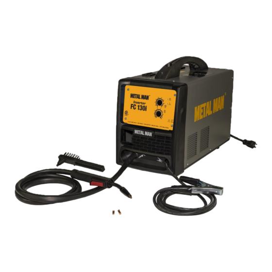
Electromagnetic Field -Electromagnetic fields can interfere with various electrical and electronic devices such as pacemakers. -Consult your doctor before using any electric arc welder or cutting device -Keep people with pacemakers away from your welding area when welding. -Do not wrap cable around your body while welding. -Wrap MIG gun and ground cable together whenever possible. - Page 7 DESCRIPTION METAL MAN FC130i 120 volt input, 130 amp DC output flux core only wire feed welders is economical and easy to use. It requires no shielding gas and welds 8 gauge to 3/16" mild steel materials with .030" or .035" flux core wires on 4" or 8" spools. This unit features a dialed voltage range, a set up chart, a cooling fan, trigger activated arc, overload protection, 8-1/2 ft torch with Tweco style series 11 replacement parts and 6 ft ground cable and clamp.
-
Page 8: Installation
Welding Cable and Torch The welding wire is driven through the welding cable and torch to the work piece. It is attached to the drive system; the gun trigger activates the drive motor. Power Indicator When the machine is turned on, the power indicator will be on. Alarm Indicator When the thermal indictor is on, it shows the machine is overloaded and the internal temperature is too high. - Page 9 an extension cord, it must be a size #12 or larger. Check with a qualified electrician and your local electrical codes for your specific area. Do not use an extension cord over 25 ft. in length. 3. INSTALL THE WIRE ROLLER - The wire roller has been factory installed. However, check to make certain the correct wire groove is in place to accommodate the size of wire you are using.
- Page 10 NOTE: - Metal thinner than 18 gauge cannot be welded with this machine. Attempting to do so will cause burn through in the metal you are intending to weld. - Do not use rusty wire. Remove any wire that is rusty. If the whole spool is rusty, discard it and use another roll.
- Page 11 8 Inch 4 Inch g. The welder can use either 4 inch or 8 inch spools. See the following figure for additional reference. The wing nut controls the tension on the spool. h. Setting the wire spool tension. a) Turn the spool of wire with one hand. b) Increase the spool tension by tightening (turn clockwise) the wing nut while turning the spool.
- Page 12 l. Insert the wire into the inlet guide tube, feed it across the drive roller and into the torch assembly about six inches. -Make certain that the welding wire is actually going into the torch liner. If not, the wire will jam up in the mechanism.
-
Page 13: Operation
a. Press the trigger on the torch. b. Turn the drive tension adjustment knob clockwise until the wire seems to feed smoothly without slipping. OPERATION • High voltage danger from power source! Consult a qualified electrician for proper installation of receptacle. This cutter must be grounded while in use to protect the operator from electrical shock. - Page 14 the weld puddle and to direct the force of the arc. 6. DISTANCE FROM THE WORK PIECE - If the nozzle is held off the work piece, the distance between the nozzle and the work piece should be kept constant and should not exceed 1/4 inch or the arc may begin sputtering, signaling a loss in welding performance.
- Page 15 ELECTRIC SHOCK CAN CAUSE INJURY OR DEATH! To prevent ELECTRIC SHOCK, do not perform any welding while standing, kneeling, or lying directly on the grounded work piece. 8.1 Moving the torch Torch travel refers to the movement of the torch along the weld joint and is broken into two elements: Direction and Speed.
- Page 16 8.3 Welding position FLAT POSITION is easiest of the welding positions and is most commonly used. It is best if you can weld in the flat position if at all possible, as good results are easier to achieve. HORIZONTAL POSITION is performed very similarly to the flat weld except that angle B (see HOLDING THE TORCH) is such that the wire, directed more toward the metal above the weld joint is to help prevent the weld puddle from running downward while still allowing slow enough travel speed.
- Page 17 OVERHEAD POSITION is the most difficult welding position. Angle A (see HOLDING THE TORCH) should be maintained at 60 degrees. Maintaining this angle will reduce the chances of molten metal falling into the nozzle. Angle B should be held at zero degrees so that the wire is aiming directly into the weld joint.
- Page 18 8.5 Spot welding There are three methods of spot welding: Burn-Through, Punch and Fill, and Lap. Each has advantages and disadvantages depending on the specific application as well as personal preference. 1. The BURN-THROUGH METHOD welds two overlapped pieces of metal together by burning through the top piece and into the bottom piece.
-
Page 19: Maintenance
Maintain your FC130i. It is recommended that the general condition of any FC130i be examined before it is used. Keep your FC130i in good repair by adopting a program of conscientious repair and maintenance. Have necessary repairs made by qualified service personnel. - Page 20 ELECTRICAL DIAGRAM Page of 24...
-
Page 21: Diagram & Parts List
DIAGRAM & PARTS LIST Page of 24... - Page 22 Reference # Part# Description Qty. 105200426 HANDLE 145200017 FC130i SET-UP GUIDE 145200036 ENCLOSURE 105800002 POWER CORD 145200016 FRONT PANEL DECAL FC130i 105200046 SWITCH 145200037 BACK PANEL 105200468 145200038 BASE PLATE 105500033 FEET 145200014 PLASTIC FRONT PANEL 105200449 CABLE COVER 105200030...
- Page 23 Reference # Part# Description Qty. 105200034 FLUX CORE NOZZLE 105200043 .030 CONTACT TIP 105200033 CONTACT TIP ADAPTER 105200104 TORCH INSULATOR 105200105 TORCH LINER 105200106 TORCH HEAD TUBE For replacement parts and technical questions contact the technical help line at 1-888-762-4045 Page of 24...
- Page 24 METAL MAN WORK GEAR CO. 1760 Prospect Ct, Suite 120 Appleton, WI 54914 888-762-4045 www.metalmangear.com Made in China Page of 24...
Need help?
Do you have a question about the FC130i and is the answer not in the manual?
Questions and answers