Table of Contents
Advertisement
Quick Links
MIG 180DVT
OWNER'S MANUAL
03/2018
WARNING:
Read carefully and understand all ASSEMBLY AND OPERATION
INSTRUCTIONS before operating. Failure to follow the safety rules and other
basic safety precautions may result in serious personal injury.
WELDER WARRANTY
www.MetalManGear.com
Toll Free Help 888-762-4045
Advertisement
Table of Contents

Related Manuals for Metal Man MIG 180DVT


Summary of Contents for Metal Man MIG 180DVT
- Page 1 MIG 180DVT OWNER’S MANUAL 03/2018 WARNING: Read carefully and understand all ASSEMBLY AND OPERATION INSTRUCTIONS before operating. Failure to follow the safety rules and other basic safety precautions may result in serious personal injury. WELDER WARRANTY www.MetalManGear.com Toll Free Help 888-762-4045...
- Page 2 Limited to the warranty periods below, Metal Man Work Gear Co will repair or replace the item under warranty that fails due to defects in material and workmanship. Metal Man Work Gear must be notified within 30 days of the failure, so as to provide instructions on how to proceed with the repair of your welder and warranty claim processing.
-
Page 3: General Safety Rules
GENERAL SAFETY RULES WARNING: Read and understand all instructions. Failure to follow all instructions listed below may result in serious injury. CAUTION: Do not allow persons to operate or assemble this welder until they have read this manual and have developed a thorough understanding of how the welder works. WARNING: The warnings, cautions, and instructions discussed in this instruction manual cannot cover all possible conditions or situations that could occur. - Page 4 -Connect ground lead as close to the area being welded as possible to ensure a good ground. -Do not allow any body part to come in contact with the welding wire if you are in contact with the material being welded, ground or electrode from another welder. -Do not weld if you are in an awkward position.
- Page 5 UV and IR Arc Rays The welding arc produces ultraviolet (UV) and infrared (IR) rays that can cause injury to your eyes and skin. Do not look at the welding arc without proper eye protection. -Always use a helmet that covers your full face from the neck to top of head and to the back of each ear.
-
Page 6: Technical Specifications
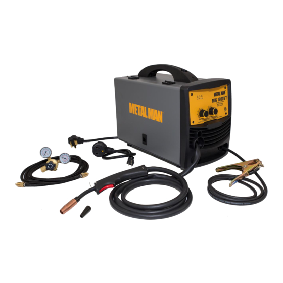
-Wrap MIG gun and ground cable together whenever possible. -Keep MIG gun and ground cables on the same side of your body. Shielding Gas Cylinders Can Explode High pressure cylinders can explode if damaged, so treat them carefully. -Never expose cylinders to high heat, sparks, open flames, mechanical shocks or arcs. -Do not touch cylinder with MIG gun. - Page 7 It features infinite wire feed speed control and voltage control, giving you total control to tune in the arc you want. The MIG 180DVT also features a cooling fan and thermal overload protection to help protect your investment. The Inverter Technology is evident from the moment you take this unit out of the box.
- Page 8 Power Indicator When the unit is plugged in and the power switch on the back panel is in the “On” position, the power indicator light will come on indicating power has been applied to the unit. Thermal Indicator If the duty cycle of the welder is exceeded the internal temperature will exceed safe temperatures and the machine will shut down.
-
Page 9: Installation
INSTALLATION Electrical Shock • High voltage danger from power source! Consult a qualified electrician for proper installation of receptacle. This welder must be grounded while in use to protect the operator from electrical shock. • Do not remove grounding prong or alter the plug in any way. Use only the supplied adapter between the welder’s power cord and the power source receptacle. - Page 10 h. Close the door to the welder drive compartment. 5. INSTALL THE WIRE a. Select welding wire - We recommend the usage of .030 Wire on this unit. However, .023 - .035 wire may be used. Both four-inch and eight-inch wire spools can be used on this welder.
- Page 11 change the drive roller as described in Section 4 above. c. Remove the packaging from the spool of wire and then identify the leading end of the wire secured on the edge of the spool. DO NOT UNHOOK IT AT THIS TIME. d.
- Page 12 Loosen the tension adjusting knob holding the drive tension arm in place and lift the tension arm up off the drive roller. Insert the wire into the inlet guide tube, feed it across the drive roller and into the torch assembly about six inches.
- Page 13 8. GAS INSTALLATION Shielding gas cylinders and high pressure cylinders can explode if damaged, so treat them carefully. • Never expose cylinders to high heat, sparks, open flames, mechanical shocks or arcs. • Do not weld on the cylinder. • Always secure cylinder upright to a cart or stationary object.
- Page 14 (1) Gas Bottle Valve (2) Gas Flow Gauge (Set at 20 CFM) (3) Gas Pressure Gauge (4) Regulator (5) Gas Flow Adjuster (6) Gas Hose Connection (7) Gas Cylinder g. Open the Gas Bottle Valve on the cylinder of gas. h.
-
Page 15: Mig Operation
MIG OPERATION • High voltage danger from power source! Consult a qualified electrician for proper installation of receptacle. This welder must be grounded while in use to protect the operator from electrical shock. • Do not remove grounding prong or alter the plug in any way. Use only the supplied adapter between the welder’s power cord and the power source receptacle. - Page 16 6. DISTANCE FROM THE WORK PIECE - If the nozzle is held off the work piece, the distance between the nozzle and the work piece should be kept constant and should not exceed 1/4 inch or the arc may begin sputtering, signaling a loss in welding performance. 7.
- Page 17 ELECTRIC SHOCK CAN CAUSE INJURY OR DEATH! To prevent ELECTRIC SHOCK, do not perform any welding while standing, kneeling, or lying directly on the grounded workpiece. 8.1 Moving the torch Torch travel refers to the movement of the torch along the weld joint and is broken into two elements: Direction and Speed.
- Page 18 8.3 Welding position FLAT POSITION is easiest of the welding positions and is most commonly used. It is best if you can weld in the flat position if at all possible as good results are easier to achieve. HORIZONTAL POSITION is performed very similarly to the flat weld except that angle B (see HOLDING THE TORCH) is such that the wire, directed more toward the metal above the weld joint is to help prevent the weld puddle from running downward while still allowing slow enough travel speed.
- Page 19 the weld joint. If you experience excessive dripping of the weld puddle, select a lower heat setting. Also, the weave bead tends to work better than the stringer. 8.4 Multiple pass welding Butt Weld Joints When butt welding thicker materials, you will need to prepare the edges of the material to be joined by grinding a bevel on the edge of one or both pieces of the metal being joined.
- Page 20 8.5 Spot welding There are three methods of spot welding: Burn-Through, Punch and Fill, and Lap. Each has advantages and disadvantages depending on the specific application as well as personal preference. 1. The BURN-THROUGH METHOD welds two overlapped pieces of metal together by burning through the top piece and into the bottom piece.
-
Page 21: Maintenance
8.6 SPOT WELDING INSTRUCTIONS 1. Select the wire diameter and heat setting recommended above for the method of spot welding you intend to use. 2. Tune in the wire speed as if you were going to make a continuous weld. 3. - Page 22 MAIN CIRCUIT CHART Page of 25...
-
Page 23: Diagram & Parts List
DIAGRAM & PARTS LIST Page of 25... - Page 24 REFERENCE PART NUMBER DESCRIPTION 105200426 HANDLE 145200018 DOOR 145200020 SET UP CHART MIG 180DVT 105200040 DOOR LATCH 105200427 SPOOL HOLDER 105200428 WELD OUTPUT TERMINAL BLACK 105200429 WELD OUTPUT TERMINAL RED 105200430 WIRE FEED ASSEMBLY 105200431 MIDDLE PANEL 105200432 FRONT PANEL PC BOARD...
- Page 25 METAL MAN WORK GEAR COMPANY 1760 PROSPECT CT #120 APPLETON WI 54914 www.metalmangear.com Made in China Page of 25...
Need help?
Do you have a question about the MIG 180DVT and is the answer not in the manual?
Questions and answers