Table of Contents
Advertisement
Quick Links
Advertisement
Table of Contents

Related Manuals for Metal Man MP140T


Summary of Contents for Metal Man MP140T
- Page 1 MP140T OWNER’S MANUAL 03/2018 WARNING: Read carefully and understand all ASSEMBLY AND OPERATION INSTRUCTIONS before operating. Failure to follow the safety rules and other basic safety precautions may result in serious personal injury. www.MetalManGear.com Toll Free Help 888-762-4045...
-
Page 2: Limited Warranty
Limited to the warranty periods below, Metal Man Work Gear Co will repair or replace the item under warranty that fails due t o defects in material and workmanship. Metal Man Work Gear must be notified within 30 days of the failure, so as to provide instructions on how to proceed with the repair of your welder and warranty claim processing. -
Page 3: General Safety Rules
GENERAL SAFETY RULES WARNING: Read and understand all instructions. Failure to follow all instructions listed below may result in serious injury. CAUTION: Do not allow persons to operate or assemble this unit until they have read this manual and have developed a thorough understanding of how this unit works. WARNING: The warnings, cautions, and instructions discussed in this instruction manual cannot cover all possible conditions or situations that could occur. - Page 4 material being welded, ground or electrode from another welder. -Do not weld if you are in an awkward position. Always have a secure stance while welding to prevent accidents. Wear a safety harness if working above ground. -Do not drape cables over or around your body. -Wear a full coverage helmet with appropriate shade (see ANSI Z87.1 safety standard) and safety glasses while welding.
- Page 5 ear. -Use a lens that meets ANSI standards and safety glasses. For welders under 160 Amps output, use a shade 10 lens; for above 160 Amps, use a shade 12. Refer to the ANSI standard Z87.1 for more information. -Cover all bare skin areas exposed to the arc with protective clothing and shoes. Flame-retardant cloth or leather shirts, coats, pants or coveralls are available for protection.
- Page 6 Electromagnetic Field -Electromagnetic fields can interfere with various electrical and electronic devices such as pacemakers. -Consult your doctor before using any electric arc welder or cutting device -Keep people with pacemakers away from your welding area when welding. -Do not wrap cable around your body while welding. -Wrap MIG gun and ground cable together whenever possible.
-
Page 7: Technical Specifications
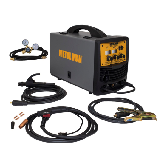
24-1/4 lb. DESCRIPTION The Metal Man MIG 140T is a portable DC inverter wire feed welder capable of welding with solid wire (with shielding gas) or with flux core wire. It comes ready to accept part number EZFSG2 optional Spool Gun for welding aluminum. This machine also has smooth DC stick capabilities and the ability to perform lift start DC TIG welding on steel and stainless steel materials with part number ACTT1, the optional TIG Torch. - Page 8 Spool Gun/ MIG Torch/Stick Spot Timer Indicator Digital Regulator/ Welding Selector On/Off Lights Meters Flowgauge w/Gas Hose Spot Time Adjustment Voltage Setting Electrode Holder And Wire Speed Cable & Amperage Control Ground Cable And Clamp MIG Torch POWER INDICATOR LIGHT In the “OFF”...
- Page 9 Adjustable spot timer allows you to set a time factor for consistently timed spot welds. This control turns the spot welder function ON or OFF. SPOOL GUN/MIG TORCH/STICK WELDING SELECTOR When normal MIG welding, this switch should be turned in “MIG” position. When using the spool gun, the switch should be in “spool gun”...
- Page 10 certain to completely slide the torch all the way in. Slightly twist to assist with pushing the torch to the back of the receptacle. The retaining bolt can then be tightened, making certain the bolt sets down into the retaining groove on the back of the MIG torch. Socket 5-Pin Trigger Receptacle...
- Page 11 2. OPTIONAL SPOOL GUN ASSEMBLY 2.1 This unit is set-up to accept the Optional Spool Gun. 2.2 The Spool Gun has three connection points at the back of the Spool Gun. (1) The gas connection is a slide on quick connector. (2) The weld power connection has a round ring connection. (3) The snap-on trigger connection is 5-Pin.
- Page 12 2.5 Open the wire compartment door. 2.6 Connect the gas connection quick connector to the gas connector (1) on the back panel of the wire compartment. 2.7 Connect the weld power connection to the bolt on the top of the MIG connector (2). 2.8 Connect the 5-Pin trigger connector to the 5-Pin receptacle on the front of the machine (3).
-
Page 13: Installation
4.4 Connect the TIG torch weld cable to the Negative (-) weld output connection. 4.5 Set desired amperage on the amperage control knob on the front panel of the welder. 4.6 Turn on the input power switch on the welder. 4.7 Turn on the regulator on the bottle of shielding gas and adjust the regulator to approximately 20 CFH. - Page 14 b. Remove the drive tension by loosening the Drive Tension Adjuster (1) and moving the Drive Tension Adjustor away from the Drive Tension Arm (2). Lift the Drive Tension Arm away from the Drive Roller (3). c. If there is wire already installed in the welder, roll it back onto the wire spool by hand-turning the spool clockwise.
- Page 15 Contact Flux Core Nozzle Nozzle Make sure the proper groove on the drive roller is in place for the wire installed. If not, change the drive roller as described in Section 3. Remove the packaging from the spool of wire and then identify the leading end of the wire secured on the edge of the spool.
- Page 16 Setting the wire spool tension. a) Turn the spool of wire with one hand. b) Increase the spool tension by tightening (turn clockwise) the wing nut while turning the spool. Turn the spool while tightening the wing nut until the spool slows down and you feel a slight drag.
-
Page 17: Gas Installation
contact tip into the end of the torch and hand-tighten securely. w. Install the nozzle on the torch assembly. Cut off excess wire that extends past the end of the nozzle more than 1/4 inch. Turn the welder ON. 5. SETTING THE DRIVE ROLL TENSION •... - Page 18 (1) Gas Bottle Valve (4) Regulator (2) Gas Flow Gauge (Set at 20 (5) Gas Flow Adjuster CFM) (6) Gas Hose Connection (3) Gas Pressure Gauge (7) Gas Cylinder g. Open the Gas Bottle Valve on the cylinder of gas. h.
-
Page 19: Mig Operation
MIG OPERATION • High voltage danger from power source! Consult a qualified electrician for proper installation of receptacle. This cutter must be grounded while in use to protect the operator from electrical shock. • Do not remove grounding prong or alter the plug in any way. Use only the supplied adapter between the welder's power cord and the power source receptacle. -
Page 20: Welding Techniques
6. DISTANCE FROM THE WORK PIECE - If the nozzle is held off the work piece, the distance between the nozzle and the work piece should be kept constant and should not exceed 1/4 inch or the arc may begin sputtering, signaling a loss in welding performance. 7. - Page 21 ELECTRIC SHOCK CAN CAUSE INJURY OR DEATH! To prevent ELECTRIC SHOCK, do not perform any welding while standing, kneeling, or lying directly on the grounded work piece. 8.1 Moving the torch Torch travel refers to the movement of the torch along the weld joint and is broken into two elements: Direction and Speed.
- Page 22 8.3 Welding position FLAT POSITION is easiest of the welding positions and is most commonly used. It is best if you can weld in the flat position if at all possible as good results are easier to achieve. HORIZONTAL POSITION is performed very similarly to the flat weld except that angle B (see HOLDING THE TORCH) is such that the wire, directed more toward the metal above the weld joint is to help prevent the weld puddle from running downward while still allowing slow enough travel speed.
- Page 23 falling into the nozzle. Angle B should be held at zero degrees so that the wire is aiming directly into the weld joint. If you experience excessive dripping of the weld puddle, select a lower heat setting. Also, the weave bead tends to work better than the stringer. 8.4 Multiple pass welding Butt Weld Joints: When butt welding thicker materials, you will need to prepare the edges of the material to be joined by grinding a bevel on the edge of one or both pieces of the metal being joined.
-
Page 24: Spot Welding Instructions
8.5 Spot welding There are three methods of spot welding: Burn-Through, Punch and Fill, and Lap. Each has advantages and disadvantages depending on the specific application as well as personal preference. 1. The BURN-THROUGH METHOD welds two overlapped pieces of metal together by burning through the top piece and into the bottom piece. -
Page 25: Setting Up The Work Piece
1. Select the wire diameter and heat setting recommended above for the method of spot welding you intend to use. 2. Tune in the wire speed as if you were going to make a continuous weld. 3. Hold the nozzle piece completely perpendicular to and about 1/4 inch off the work piece. 4. -
Page 26: Ground Clamp Connection
2. GROUND CLAMP CONNECTION Clear any dirt, rust, scale, oil or paint on the ground clamp. Make certain you have a good solid ground connection. A poor connection at the ground clamp will waste power and heat. Make sure the ground clamp touches the metal. 3. - Page 27 4.1. When proper rod is used: 4.1.a. The bead will lay smoothly over the work without ragged edges 4.1.b. The base metal puddle will be as deep as the bead that rises above it 4.1.c. The welding operation will make a crackling sound similar to the sound of eggs frying 4.2.
- Page 28 work piece should be between 10 and 30 degrees. This will allow for good penetration, with minimal spatter. 6.2 Striking the arc EXPOSURE TO A WELDING ARC IS EXTREMELY HARMFUL TO THE EYES AND SKIN! Prolonged exposure to the welding arc can cause blindness and burns. Never strike an arc or begin welding until you are adequately protected.
- Page 29 The weave bead: Used when you want to deposit metal over a wider space than would be possible with a stringer bead. It is made by weaving from side to side while moving with the electrode. It is best to hesitate momentarily at each side before weaving back the other way. 6.4 Welding position Flat position: It is easiest of the welding positions and is most commonly used.
- Page 30 accumulation of dirty metal scale on the finished weld. Slag should be removed by using a chipping hammer. PEENING THE SLAG FROM A WELD JOINT CAUSES SMALL CHIPS OF METAL TO FLY THROUGH THE AIR! Metallic chips flying through the air can cause eye injury or injury to other parts of the head, hands or exposed portions of the body.
-
Page 31: Maintenance
b. Rest the TIG torch nozzle on the work piece making sure to not touch the installed tungsten electrode. c. Twist the torch to make contact between the work piece and the tungsten. d. Lift torch away from the work piece about 1/8 inch. e. -
Page 32: Troubleshooting
TROUBLESHOOTING SYMPTOM POSSIBLE CAUSE CORRECTIVE ACTION Unit does not power up Unit is not plugged in Plug in unit Input power circuit breaker not on Reset input power circuit breaker The main power switch is not Replace main power switch working Protection indicator is on The internal temperature is too... - Page 33 MAIN CIRCUIT CHART Page of 36...
-
Page 34: Diagram & Parts List
DIAGRAM & PARTS LIST Reference # Part# Description Qty. 105200426 HANDLE 145200019 ENCLOSURE 105200041 WARNING LABEL 145200001 NEED HELP LABEL 105300155 POWER SWTICH 105800001 GAS VALVE 105800002 POWER CORD 105800003 BACK PANEL 105800004 105800005 MAIN PC BOARD 105200437 BOTTOM 105800006 WIRE FEED CONTROL BOARD 105800007 FEET... - Page 35 HOLDER END, LOOSE 105200011 SPRING 105200013 BOLT 105200014 HOLDER END, FIXED 105200040 DOOR LATCH 145200023 DOOR SET-UP GUIDE MP140T 105200425 DOOR HINGE 105200103 GROUND CABLE AND CLAMP 105200069 CLAMP ONLY OWNER’S MANUAL MP220SiDV LCD 145200024 105200081 GAS HOSE TO REGULATOR...
- Page 36 Metal Man Work Gear Company 1760 Prospect Ct #120 Appleton, WI 54914 w w w . m e t a l m a n g e a r . c o m 8 8 8 - 7 6 2 - 4 0 4 5...
Need help?
Do you have a question about the MP140T and is the answer not in the manual?
Questions and answers