Table of Contents
Advertisement
Quick Links
Advertisement
Table of Contents

Related Manuals for Metal Man MIG140 Series


Summary of Contents for Metal Man MIG140 Series
- Page 1 MIG140x OWNER’S MANUAL RECONDITIONED WARNING: Read carefully and understand all ASSEMBLY AND OPERATION INSTRUCTIONS before operating. Failure to follow the safety rules and other basic safety precautions may result in serious personal injury.
- Page 2 Page of 28...
-
Page 3: Warranty
Limited to the warranty periods below, Metal Man Work Gear Co will repair or replace the item under warranty that fails due to defects in material and workmanship. Metal Man Work Gear must be notified within 30 days of the failure, so as to provide instructions on how to proceed with the repair of your welder and warranty claim processing. -
Page 4: General Safety Rules
GENERAL SAFETY RULES WARNING: Read and understand all instructions. Failure to follow all instructions listed below may result in serious injury. CAUTION: Do not allow persons to operate or assemble this Flux Core 125 until they have read this manual and have developed a thorough understanding of how the Flux Core 125 works. - Page 5 -Connect ground lead as close to the area being welded as possible to ensure a good ground. -Do not allow any body part to come in contact with the welding wire if you are in contact with the material being welded, ground or electrode from another welder. -Do not weld if you are in an awkward position.
- Page 6 The welding arc produces ultraviolet (UV) and infrared (IR) rays that can cause injury to your eyes and skin. Do not look at the welding arc without proper eye protection. -Always use a helmet that covers your full face from the neck to top of head and to the back of each ear.
-
Page 7: Technical Specifications
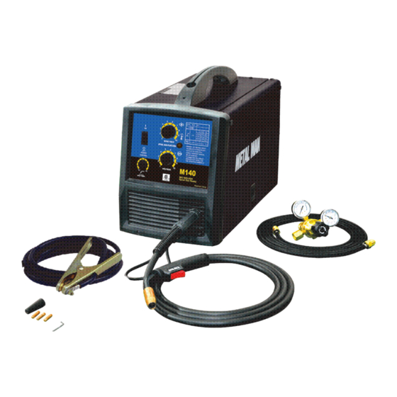
-Do not put hands or fingers near moving parts such as drive rolls of fan Metal Man MIG 140x USE AND CARE Do not modify the MIG 140x in any way. Unauthorized modification may impair the function and/or safety and could affect the life of the equipment. - Page 8 DESCRIPTION The Metal Man MIG 140x is a portable DC wire feed welder capable of welding with solid wire (with shielding gas) or flux core wire. It is powered by AC single phase 120V (110-120V), 60HZ/20amp with time delayed fuse or circuit breaker. It features infinite wire feed speed control and voltage control giving you total control to tune in the arc you want.
-
Page 9: Installing The Handle
Ground Cable and Clamp The ground cable and clamp are attached to the work piece to complete the circuit allowing the flow of current needed to weld. Welding Cable and Torch The welding wire is driven through the welding cable and torch to the work piece. It is attached to the drive system;... - Page 10 3. INSTALL THE TORCH A) Locate the set screw inside the front panel, at the front of the drive system where the MIG torch is inserted. Loosen set screw. Screw B) Insert the MIG torch into the MIG torch receptacle on the front of the machine. Make certain to slide the MIG torch all the way into the receptacle.
-
Page 11: Installing The Wire
5. INSTALL THE WIRE ROLLER – Before installing any welding wire into the unit, the proper sized groove on the drive roll must be placed into position. A) Open the wire compartment door B) Loosen the drive tension adjustor Drive Tension Drive Adjustor Roll... - Page 12 6.1 Remove the nozzle and contact tip from the end of the torch assembly. 6.2 Make sure the proper groove on the drive roller is in place for the wire installed. If not, change the drive roller as described in Section 5. 6.3 Remove the packaging from the spool of wire and then identify the leading end of the wire secured on the edge of the spool.
- Page 13 when the trigger is released. Readjust the spool tension using the wing nut as necessary to correct for either problem. 6.7 With the welder disconnected form the power source, remove the leading end of the wire from the spool. Hold on to it securely, so as not to allow unspooling or tangling of the wire as it will result in tangled wire and feeding problems.
-
Page 14: Gas Installation
5. SETTING THE DRIVE ROLL TENSION Arc flash can injure eyes! To reduce the risk of arc flash, make certain that the wire coming out of the end of the torch does not come in contact with the work piece, ground clamp, or any grounded material during the drive tension setting process or arcing will occur. - Page 15 6.2 Connect one end of the gas hose to the gas hose connection on the back of the welder. Connect the other end of the gas hose to the gas hose connection on the supplied regulator/flowgauge. 6.4 Before installing the regulator, it is good practice to make certain no debris is in the gas bottle connection.
-
Page 16: Operation
OPERATION High voltage danger from power source! Consult a qualified electrician for proper installation of receptacle at the power source. This welder must be grounded while in use to protect the operator from electrical shock. If you are not sure if your outlet is properly grounded, have it checked by a qualified electrician. -
Page 17: Welding Techniques
6. DISTANCE FROM THE WORK PIECE - If the nozzle is held off the work piece, the distance between the nozzle and the work piece should be kept constant and should not exceed 1/4 inch or the arc may begin sputtering, signaling a loss in welding performance. 7. - Page 18 ELECTRIC SHOCK CAN KILL! To prevent ELECTRIC SHOCK, do not perform any welding while standing, kneeling, or lying directly on the grounded workpiece. 8.1 Moving the torch Torch travel refers to the movement of the torch along the weld joint and is broken into two elements: Direction and Speed.
- Page 19 8.3 Welding position FLAT POSITION is easiest of the welding positions and is most commonly used. It is best if you can weld in the flat position if at all possible as good results are easier to achieve. HORIZONTAL POSITION Is performed very much the same as the flat weld except that angle B (see HOLDING THE TORCH) is such that the wire, directed more toward the metal above the weld joint is to help prevent the weld puddle from running downward while still allowing slow enough travel speed.
- Page 20 falling into the nozzle. Angle B should be held at zero degrees so that the wire is aiming directly into the weld joint. If you experience excessive dripping of the weld puddle, select a lower heat setting. Also, the weave bead tends to work better than the stringer. 8.4 Multiple pass welding Butt Weld Joints When butt welding thicker materials, you will need to prepare the edges of the material to be joined by grinding a bevel on the edge of one or both pieces of the metal being joined.
- Page 21 8.5 Spot welding There are three methods of spot welding: Burn-Through, Punch and Fill, and Lap. Each has advantages and disadvantages depending on the specific application as well as personal preference. 1. The BURN-THROUGH METHOD welds two overlapped pieces of metal together by burning through the top piece and into the bottom piece.
-
Page 22: Maintenance
MAINTENANCE • Maintain your MIG 140x. It is recommended that the general condition of any welder be examined before it is used. Keep your welder in good repair by adopting a program of conscientious repair and maintenance. Have necessary repairs made by qualified service personnel. - Page 23 MAIN CIRCUIT CHART Page of 28...
-
Page 24: Diagram & Parts List
DIAGRAM & PARTS LIST Page of 28... - Page 25 Reference number Description Part number Door Latch 2.08.07.803 left side panel 1.1.01.04.0437 grounding cable 1.2.08.02.0202 Wire feeder 2.07.40.610 MIG gun 1.2.07.02.2471 torch socket 2.20.02.208 connection box 2.05.17.027 front panel 2.05.05.960 potentiometer 2.07.10.663 diode 2.07.28.211 potentiometer 2.07.10.663 Switch with potentiometer 2.07.10.668 wave switch 2.07.80.202 main transformer...
- Page 26 Page of 28...
- Page 27 Page of 28...
- Page 28 METAL MAN WORK GEAR COMPANY 1760 PROSPECT CT #120 APPLETON WI 54914 www.metalmangear.com Made in China Page of 28...
Need help?
Do you have a question about the MIG140 Series and is the answer not in the manual?
Questions and answers