Table of Contents
Advertisement
Quick Links
Item #1011 954 848
Model # 59065
Basic Model # 52-FERN-REV2-08022024
USE AND CARE GUIDE
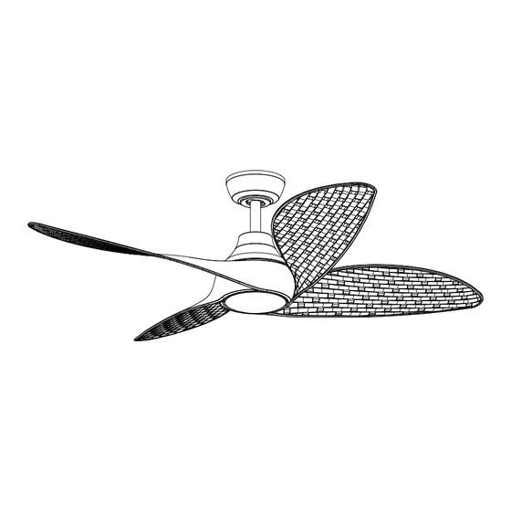
FERNBROOKE 52-INCH CEILING FAN
Questions, problems, missing parts?
Before returning to the store, call Hampton Bay Customer Service
8 a.m. - 7 p.m., EST, Monday-Friday, 9 a.m. - 6 p.m., EST, Saturday
1-855-HD-HAMPTON
HAMPTONBAY.COM
To view an instructional video on how to install this product:
1. Go to www.homedepot.com and enter either the Item or Model number, found
in the top right corner of the cover of this instruction manual, in the search field.
2. Click on your product from the list of search results and click on the video link
in the "Product Overview" section.
Scan for text based
Scan for online product
customer support
warranty information
THANK YOU
We appreciate the trust and confidence you have placed in Hampton Bay through the purchase of this ceiling fan. We strive to continually
create quality products designed to enhance your home. Visit us online to see our full line of products available for your home improvement
needs. Thank you for choosing Hampton Bay!
Advertisement
Table of Contents

Related Manuals for HAMPTON BAY FERNBROOKE 52


Summary of Contents for HAMPTON BAY FERNBROOKE 52
- Page 1 THANK YOU We appreciate the trust and confidence you have placed in Hampton Bay through the purchase of this ceiling fan. We strive to continually create quality products designed to enhance your home. Visit us online to see our full line of products available for your home improvement...
-
Page 2: Table Of Contents
Table of Contents Safety Information ........2 Installation . -
Page 3: Warranty
Warranty The supplier warrants the fan motor to be free from defects in workmanship and material present at time of shipment from the factory for a lifetime after the date of purchase by the original purchaser. The supplier warrants that the light kit, excluding any glass, to be free from defects in workmanship and material at the time of shipment from the factory for a period of three years after the date of purchase by the original purchaser. -
Page 4: Hardware Included
Pre-Installation (continued) HARDWARE INCLUDED NOTE: Hardware not shown to actual size. Part Description Quantity Hanger pin Locking pin Upper housing screw Top blade screw Bottom blade screw Machine screw (remote control wall cradle) Short tapered screw (remote control wall cradle) Long tapered screw (remote control wall cradle) Plastic wire connecting nut Rubber gasket... -
Page 5: Package Contents
Pre-Installation (continued) PACKAGE CONTENTS Part Description Quantity Part Description Quantity Slide-on mounting bracket Light kit fitter assembly (inside canopy) Shatter resistant shade Ball/downrod assembly Receiver Canopy Remote control Decorative motor collar cover 3-pin extension wire (motor) Fan motor assembly 3-pin extension wire (light) Blade Battery Light kit pan... -
Page 6: Installation
Installation MOUNTING OPTIONS WARNING: To reduce the risk of fire, electric shock NOTE: You may need a longer downrod to maintain proper blade clearance when installing on a steep, or personal injury, mount to an outlet box marked sloped ceiling. The maximum angle allowable is 15° “Acceptable for fan support of 35 lb (15.9 kg) or away from horizontal. -
Page 7: Assembly
Assembly - Standard Ceiling Mount Preparing for mounting NOTE: The magnet is pre-attached on the canopy bottom cover for you to remove and install easily. □ Remove the magnetic canopy bottom cover (JJ) from the canopy (C) by pulling it off. □... -
Page 8: Routing The Wires
Assembly - Standard Ceiling Mount (continued) Attaching the upper housing to the motor assembly □ Attach the upper housing (P) and rubber gasket (VV) to the fan motor assembly (E), align the three screw holes in the upper housing (P) and rubber gasket (VV) with the screw holes above the coupler on motor assembly (E), and secure the upper housing with screws (CC). -
Page 9: Assembling The Fan
Assembly - Standard Ceiling Mount (continued) Assembling the fan CAUTION: To ensure wobble-free operation and to avoid damage to the fan, the downrod (B) and the setscrew (KK) must be completely tightened. WARNING: Failure to properly install the locking pin (BB) could result in the fan becoming loose and possibly falling. -
Page 10: Installing The Receiver
Assembly - Hanging the Fan (continued) Hanging the fan Installing the receiver □ Carefully lift the fan motor assembly (E) up to the slide-on WARNING: To reduce the risk of fire or electric mounting bracket (A). shock, remember to disconnect power. The □... -
Page 11: Making Electrical Connections
Assembly - Hanging the Fan (continued) Wire Connections Making electrical connections Single Wall Switch □ On a single switch the fan and light can be turned on or off WARNING: To avoid possible electrical shock, turn the together. Make wire connections as follows, using the wire electricity off at the main fuse box before wiring. - Page 12 Assembly - Hanging the Fan (optional) Wire Connections Wire Connections Dual Wall Switch No Wall Switch □ From Fan To Receiver On a dual switch the fan and light can be turned on or off separately. Make wire connections as follows, using the 3-pin connector--------------- 3-pin connector wire nuts (II).
- Page 13 Assembly - Hanging the Fan (continued) Mounting the fan motor assembly (standard mount) WARNING: When using the standard ball/downrod mounting, the tab in the ring at the bottom of the slide-on mounting bracket (A) must rest in the groove of the hanger ball. Failure to properly seat the tab in the groove could cause damage to the wiring.
- Page 14 Assembly - Attaching the Light Kit Installing the light kit pan CAUTION: To reduce the risk of electric shock, disconnect the electrical supply circuit to the fan before installing the light fixture. □ Remove one screw (NN) from the black bracket below the fan motor assembly and loosen but do not remove the other two screws.
-
Page 15: Preparing The Remote Control
Assembly - Preparing the Remote Control Preparing the remote control NOTE: The remote control has already been paired to the ceiling fan for your convenience. If the remote control does not communicate with the fan, follow the pairing instructions below. NOTE: The remote control battery will weaken with age and should be replaced before leaking takes place, as this will damage the remote control. -
Page 16: Operating Your Fan And Remote Control
Operating Your Fan and Remote Control ALL ON/OFF Press and release the ALL button to turn the fan and light on or off. LED speed All On/Off NOTE: On start up your ceiling fan will oscillate back and indicator forth. This is NORMAL OPERATION for DC ceiling fans as it goes through its calibration cycle. - Page 17 Assembly - Mounting the remote wall cradle NOTE: The remote wall cradle is designed to allow you to access an existing switch. The remote wall cradle can be mounted on the wall or to the face plate of a standard toggle switch or a paddle switch. Follow the instructions below for the option that best suits your needs.
-
Page 18: Care And Cleaning
Care and Cleaning WARNING: Make sure the power is off before cleaning your fan. □ Because of the fan’s natural movement, some connections may become loose. Check the support connections, brackets, and blade attachments twice a year. Make sure they are secure. It is not necessary to remove the fan from the ceiling. □... - Page 19 Questions, problems, missing parts? Before returning to the store, call Hampton Bay Customer Service 8 a.m. – 7 p.m., EST, Monday – Friday, 9 a.m. – 6 p.m., EST, Saturday 1-855-HD-HAMPTON HAMPTONBAY.COM Retain this manual for future use. FCC Statement: This equipment has been tested and found to comply with the limits for a Class B digital device, pursuant to Part 15 of the FCC Rules. These limits are designed to provide reasonable protection against harmful interference in a residential installation.
Need help?
Do you have a question about the FERNBROOKE 52 and is the answer not in the manual?
Questions and answers