
Related Manuals for Magus BIO VD350 LCD


Summary of Contents for Magus BIO VD350 LCD
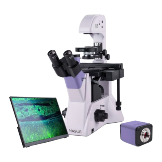
- Page 1 M AG U S B I O V D 3 5 0 LC D B I OLOG ICA L IN V ERT ED D I G I TA L MI CRO S C O P E U S E R M A N U A L...
-
Page 2: Safety Precautions
Before using the microscope, please read this user manual carefully to study the instrument design, operation modes and procedures, operational limitations, and safety precautions. Due to the continuous improvements in the microscope design, this manual may not reflect minor design changes that do not affect the microscope performance and operation procedures. - Page 3 12. Bulb installation: – Do not touch the glass surface of the bulb with your bare hands. When installing the bulb, wear gloves or wrap the bulb with a cotton cloth. – Use a clean cotton cloth moistened with alcohol-based disinfectant to wipe dirt off the surface of the bulb.
-
Page 4: Table Of Contents
Using the monitor 5 PHASE-CONTRAST TECHNIQUE 6 USING OPTIONAL EQUIPMENT Eyepiece with a scale Using a calibration slide with a camera 7 TROUBLESHOOTING 8 SCOPE OF DELIVERY 9 CARE AND MAINTENANCE Replacing the bulb and the fuse Maintenance 10 MAGUS WARRANTY... -
Page 5: Description Of The Microscope
MAGUS Bio VD350 LCD Biological Inverted Digital Microscope has been designed and tested in accordance with the international safety standards. If properly used, the microscope is safe for the customer’s health, life, property, and the environment. Proper maintenance of the microscope is a prerequisite for its reliable and safe operation. - Page 6 Windows 8/10/11 (32 and 64 bit), Mac OS X, Linux, up to 2.8 GHz Intel Core 2 System requirements or higher, minimum 4GB RAM, USB 2.0 ports, RJ45, CD-ROM, 19" or larger display (with USB connection) Software HDMI: built-in, USB: MAGUS View Mount type C-mount Body material Metal...
-
Page 7: Microscope Kit
Display refresh rate, Hz Type of matrix backlight LED backlight lifetime, h 50000 Interface HDMI Power supply AC 110–220V, DC 5–12V/1A (Type-C) Power consumption, W 12 (maximum) Dimensions without package 250mm×580mm×532mm (WxHxD) Package dimensions 345mm×730mm×495mm (WxHxD) Weight 16.8kg Weight with package 20.3kg * Not included in the kit, available on request. - Page 8 Fig. 1. MAGUS Bio VD350 LCD Microscope. View from the left 1. Eyepieces 8. Side camera port 2. Eyepiece tubes 9. Revolving nosepiece 3. Stand 10. Condenser mount 4. ON/OFF switch 11. Lamp house 5. Coarse focusing tension adjusting knob 12.
- Page 9 Fig. 2. MAGUS Bio VD350 LCD Microscope. View from the right 1. Interpupillary distance adjustment ring 10. Objectives 2. Eyepiece tube assembly locking screw 11. Condenser moving knob 3. Knob for switching the light path 12. Condenser focus knob to the trinocular tube 13.
-
Page 10: Microscope Parts
MICROSCOPE PARTS STAND The stand has stable ergonomic design. Parts attached to the microscope stand 3 (Fig. 1): – revolving nosepiece 9 (Fig. 1) with objectives – stage 18 (Fig. 2) – condenser mount 10 (Fig. 1) – lamp house 11 (Fig. 1) –... -
Page 11: Eyepieces
The interpupillary distance is adjusted by rotating the eyepiece tubes 2 (Fig. 1) in the range of 48–75mm. The distance between the eyepieces matching the observer's interpupillary distance is marked on the adjustment scale 1 (Fig. 2). For convenience, the microscope head is inclined at 45°. Microscope head magnification: 1x. -
Page 12: Lamp House
The camera is powered via a 12V/1A AC power adapter. M ON ITO R The monitor is designed to use a visualization system of the MAGUS microscope. It is connected to the camera mounted on the microscope to display the real-time images. -
Page 13: Unpacking And Assembling The Microscope
UNPACKING AND ASSEMBLING THE MICROSCOPE The assembly procedure is given in Fig. 3. Fig. 3. Assembling the microscope 1. Unpack the microscope and check the scope of delivery using Section 8 of the User Manual. 2. Take out the stand 1 and place it on a stable work table, remove protective packaging and the dust cover. 3. -
Page 14: Brightfield Observation Procedure
BRIGHTFIELD OBSERVATION PROCEDURE SWITCHING ON T H E I LLU MI N ATI O N Before switching on the ON/OFF switch, make sure that the input voltage of the microscope power supply matches the local mains voltage. If not, do not switch on the microscope. Improper input voltage may result in a short circuit or fire. Set the ON/OFF switch 1 to "-"... -
Page 15: Adjusting The Eyepiece Tubes
ADJ U STI N G THE E YE P I ECE T UB ES Rotate the diopter adjustment ring 1 to find the position, at which the height of both eyepieces will be the same. Adjust the interpupillary distance. Adjust the distance between the eyepieces to your interpupillary distance by rotating the eyepiece tubes around the central axis until you see a single circular image when looking through the eyepieces with both... -
Page 16: Placing The Specimen
P LACI NG THE SP EC I ME N Choose the appropriate dish holder from the kit based on its shape and size (Fig. 11). Install the dish holder on the stage. Fix the slide 1 or the dish with the studied sample in it. Fig. -
Page 17: Setting Up Köhler Illumination
When using high magnification objectives, raise the objective all the way up by rotating the coarse focusing knob and enable the coarse focusing lock knob. After that, focus on the specimen using the fine focusing knob. Adjust the coarse focusing tension. The tension of the coarse focusing knob is adjustable and is preset by the manufacturer for convenient use. -
Page 18: Observing Specimens In Tall Glassware
O BSE RVI N G SP EC IME N S IN TAL L GLAS SWA R E The microscope is equipped with a stage attachment 1 that enables movement of the specimen in longitudinal (Y) and lateral (X) directions. The object is moved by Y-axis 2 and X-axis 3 coaxial knobs, as shown in Fig. -
Page 19: Calculating The Total Magnification
CALCU LATI N G T HE TOTAL M AGN IF I CAT I ON The total magnification is the eyepiece power multiplied by the objective power. For example, if the eyepiece is 10х/22mm, and the objective is 40х/0.60, the total magnification of the microscope is 10х40 = 400х. -
Page 20: Using The Monitor
– Pull the beam splitter lever 3. If the image on the screen is blurry, adjust the focus using the fine focusing knob. When choosing the camera port, keep in mind that you will view upright images in the main (trinocular) port. The image in the side port is inverted, mirrored from one of the surfaces. -
Page 21: Using Optional Equipment
Adjusting the phase-contrast device: 1. Take the 10х phase-contrast objective from the microscope kit and place it into the optical path. Swing the corresponding condenser phase annulus into the optical path – rotate the turret so that number "10" is shown in the window. Adjust the height of the condenser, as shown in Fig. -
Page 22: Using A Calibration Slide With A Camera
Work out the value for one eyepiece division using each objective by formula Е=ТL/A, where: E – eyepiece division value Т – stage division value specified on the stage micrometer (0.01mm) L – number of stage micrometer divisions A – number of eyepiece divisions. We recommend entering the obtained data in a size chart: Objective magnification Eyepiece division value... -
Page 23: Mechanical Components
OPT IC S AND I MAG E RE P RODUCTION The revolving nosepiece is not clicked Rotate the revolving nosepiece into in the observation position (the the fixed position, i.e. position the objective objective is not in the optical path) into the optical path The condenser is incorrectly Adjust the condenser –... -
Page 24: Scope Of Delivery
SCOPE OF DELIVERY The scope of delivery (Table 4) Component Note M IC RO S C OP E MAIN COMPONENTS Stand with a built-in power supply, transmitted light source, focusing mechanism, condenser mount, and trinocular tube Trinocular microscope head Revolving nosepiece Mounted on the stand Fixed stage Mounted on the stand... -
Page 25: Care And Maintenance
MO NITOR Monitor HDMI cable AC power adapter DC/DC Type-C adapter Fasteners (Allen wrench and screws) CARE AND MAINTENANCE REPL ACING T HE B U LB AN D T H E FU SE Before replacing the bulb or fuse, turn the ON/OFF switch to "0" position (off). Unplug the power cord from the power outlet. -
Page 26: Magus Warranty
8. Periodic inspection: the microscope should be regularly inspected and serviced to maintain its performance. MAGUS WARRANTY MAGUS provides a 5-year international warranty from date of purchase (valid for the entire life of the instrument). The Levenhuk company warrants the product to be free from defects in materials and workmanship. The Seller warrants that the MAGUS product you have purchased meets specification requirements, provided that the Buyer complies with terms and conditions of transport, storage, and operation of the product. - Page 28 www.magusmicro.com...
Need help?
Do you have a question about the BIO VD350 LCD and is the answer not in the manual?
Questions and answers