
Related Manuals for Magus BIO D230T


Summary of Contents for Magus BIO D230T
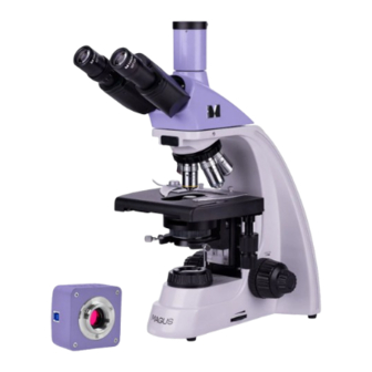
- Page 1 M AG U S B I O D 23 0T | D 2 3 0T L BI O LOG I CAL D IG I TA L MI CRO S C O P E U S E R M A N U A L...
- Page 2 Before using the microscope, please read this user manual carefully to study the instrument design, operation modes and procedures, operational limitations, and safety precautions. Due to the continuous improvements in the microscope design, this manual may not reflect minor design changes that do not affect the microscope performance and operation procedures.
- Page 3 10. Do not use any other oily substance instead of proper immersion oil made specifically for the given purpose, as this will degrade the image quality and damage the lenses. 11. Do not touch the lens surfaces with your fingers. Use a brush and special lens-cleaning solution to keep the lenses clean.
-
Page 4: Table Of Contents
5 USING OPTIONAL EQUIPMENT Darkfield condenser Darkfield slider Phase-contrast device Polarizer/analyzer set Eyepiece with a scale Using a calibration slide with a camera 6 TROUBLESHOOTING 7 SCOPE OF DELIVERY 8 CARE AND MAINTENANCE Replacing the bulb and the fuse Maintenance 9 MAGUS WARRANTY... -
Page 5: Description Of The Microscope
MAGUS Bio D230 Biological Digital Microscope has been designed and tested in accordance with the international safety standards. If properly used, the microscope is safe for the customer’s health, life, property, and the environment. Proper maintenance of the microscope is a prerequisite for its reliable and safe operation. - Page 6 Windows 8/10/11 (32bit and 64 bit), Mac OS X, Linux, up to 2.8GHz Intel Core 2 System requirements or higher, minimum 2GB RAM, USB 3.0 port, CD-ROM, 17” or larger display Software MAGUS View Mount type C-mount Body material Metal Power supply DC 5V from the computer’s USB port...
-
Page 7: Microscope Kit
Weight without package Weight with package 11kg * Not included in the kit, available on request. ** The magnification of the microscope can be increased by using additional (optional) eyepieces and objectives. The manufacturer reserves the right to make changes to the product range and specifications without prior notice. M ICROS COPE K IT This microscope kit includes the following main components: –... - Page 8 Fig. 1. MAGUS Bio D230 Microscope. View from the right 1. Eyepieces 6. Brightness adjustment ring 11. Head locking screw 2. Eyepiece tubes 7. Coarse focusing tension 12. Trinocular tube adjusting knob 3. Revolving nosepiece 13. Interpupillary distance 8. Coarse focusing knob adjustment scale 4.
- Page 9 Fig. 2. MAGUS Bio D230 Microscope. View from the left 1. Diopter adjustment ring 6. Field diaphragm ring 11. Slot for darkfield or phase- contrast slider 2. Analyzer slider insertion slot 7. Coarse focusing lock knob 12. Stand 8. Coarse focusing knob 3.
-
Page 10: Microscope Parts
2 MICROSCOPE PARTS STAND The stand 12 (Fig.2) is a one-piece structure with the base. The base has Y-shaped stable ergonomic design. Parts attached to the microscope stand: – revolving nosepiece 3 (Fig. 1) with objectives 4 (Fig. 1) – stage 3 (Fig. 2) –... -
Page 11: Eyepieces
The interpupillary distance is adjusted by rotating the eyepiece tubes 2 (Fig. 1) in the range of 48–75mm. The distance between the eyepieces matching the observer's interpupillary distance is marked on the adjustment scale 13 on the microscope head (Fig. 1). For convenience, the microscope head is inclined at 30°. -
Page 12: Condenser
The 40x and 100x objectives have a spring-loaded mount to prevent mechanical damage to the front lens and the object. If objectives are damaged, we recommend repairing them in the service center. Special immersion oil must be used with oil immersion objectives. CON DE NSE R The basic microscope kit comes with the oil immersion brightfield N.A. -
Page 13: Unpacking And Assembling The Microscope
3 UNPACKING AND ASSEMBLING THE MICROSCOPE The assembly procedure is given in Fig. 3. Fig. 3. Assembling the microscope 1. Remove the microscope from the package. 2. Check the scope of delivery using Section 7 of the User Manual. 3. Inspect the microscope and its components for damage. 4. -
Page 14: Brightfield Observation Procedure
BRIGHTFIELD OBSERVATION PROCEDURE SWITCHING ON T H E I LLU MI N ATI O N Before switching on the ON/OFF switch, make sure that the input voltage of the microscope power supply matches the local mains voltage. If not, do not switch on the microscope. Improper input voltage may result in a short circuit or fire. -
Page 15: Focusing On The Specimen
FO C US IN G ON T H E S P ECI ME N Place the 4x objective into the optical path (we recommend starting with low and medium magnification objectives that have a sufficiently large field of view and working distance). By turning the coarse focusing knob 2, raise the stage carefully until the coverslip almost touches the objective front lens. -
Page 16: Setting Up Köhler Illumination
Adjust the distance between the eyepieces to your interpupillary distance by rotating the eyepiece tubes around the central axis until you see a single circular image when looking through the eyepieces with both eyes. Fig. 8. Adjusting the interpupillary distance We recommend memorizing your interpupillary distance for future reference. -
Page 17: Using Oil Immersion Objectives
– Insert the eyepiece into the tube. – Proceed to the brightfield observations. 1. Stage 2. Condenser focus knob 3. Field diaphragm 4. Condenser centering knob 5. Aperture diaphragm Fig. 9. Centering the condenser When you switch to the objectives of other magnifications, do not change the height of the condenser, only adjust the opening of the field and aperture diaphragms. -
Page 18: Calculating The Total Magnification
CALCU LATI N G T HE TOTAL M AGN IF I CAT I ON The total magnification is the eyepiece power multiplied by the objective power. For example, if the eyepiece is 10х, and the objective is 40х, the total magnification of the microscope is 10 х... -
Page 19: Using Optional Equipment
Do it as follows: – Set the beam splitter lever 4 to the eyepiece position. While observing the specimen through the eyepieces, find a distinctive point in the field of view (an easily identifiable target, such as point S in Fig. 11а), move the specimen on the stage so that the point is in the center of the field of view, as shown in Fig. -
Page 20: Darkfield Slider
DARKF I EL D SL ID ER The darkfield slider is designed for the darkfield microscopy on objectives with apertures up to 0.9. The slider is a plate with two round openings. One opening is free for the brightfield technique. The second opening holds the darkfield diaphragm. -
Page 21: Using A Calibration Slide With A Camera
Work out the value for one eyepiece division using each objective by formula: Е = ТL/A, where E – eyepiece division value Т – stage division value specified on the stage micrometer (0.01mm) L – number of stage micrometer divisions A –... -
Page 22: Troubleshooting
6 TROUBLESHOOTING Potential problems and remedies are given in Table 3: Problem Cause Remedy ELECT RI CAL C OMPONENTS The ON/OFF switch is off Switch on the ON/OFF switch The fuse has blown Replace the fuse The bulb is burned out Switch off the power supply. - Page 23 The focal plane of the image is The specimen does not lie flat on the Place the specimen flat on the stage, tilted (brighter on one side and stage securing it with the specimen holder darker on the other) MEC HANI CA L C OMP ONE NTS The image does not remain The coarse focusing tension adjusting Adjust the coarse focusing tension...
-
Page 24: Scope Of Delivery
7 SCOPE OF DELIVERY The assembly diagram is given in Fig. 15. The scope of delivery is listed in Table 4. Camera C-mount adapter Eyepice Eyepiece with a scale Revolving nosepiece Analyzer Objective Darkfield slider Polarizer Condenser Fig. 15. The assembly diagram... - Page 25 Table 4 Component Note D230T D230TL MICROSCOPE MAIN COMPONENTS Stand (with the transmitted light illuminator, power source and focusing mechanism built into the base) ICO Infinitive trinocular microscope head Revolving nosepiece Mounted on the stand Stage Mounted on the stand REPLACEABLE PARTS Centerable Abbe condenser A 0.9 darkfield condenser...
-
Page 26: Care And Maintenance
8 CARE AND MAINTENANCE RE PL ACING T HE B ULB A N D T HE FU SE Before replacing the bulb or fuse, turn the ON/OFF switch to "0" position (off). Unplug the power cord from the power outlet. Wait about 10 minutes for the bulb to cool down. Fig. -
Page 27: Magus Warranty
7. Periodic inspection: the microscope should be regularly inspected and serviced to maintain its performance. MAGUS WARRANTY MAGUS provides a 5-year international warranty from date of purchase (valid for the entire life of the instrument). The Levenhuk company warrants the product to be free from defects in materials and workmanship. The Seller warrants that the MAGUS product you have purchased meets specification requirements, provided that the Buyer complies with terms and conditions of transport, storage, and operation of the product. - Page 28 www.magusmicro.com...
Need help?
Do you have a question about the BIO D230T and is the answer not in the manual?
Questions and answers