Advertisement
Quick Links
Advertisement

Related Manuals for Sartorius Stedim Biotech BIOSTAT STR


Summary of Contents for Sartorius Stedim Biotech BIOSTAT STR
- Page 1 Operating Instructions BIOSTAT ® Original Operating Instructions 85037-541-29 85037-541-29...
- Page 2 PDF file in various international languages. If the CD is missing, you can obtain a copy form us by specifying the order number: Order number: 85037-539-30 Sartorius Stedim Biotech GmbH Technical Editorial Department August-Spindler-Strasse 11 37079 Goettingen, Germany tech.pubs@sartorius-stedim.com...
- Page 3 Contents 1 User Information........5 6.4.3 Starting up the Temperature Control Circuit 1.1 Notes on Using these Instructions .
- Page 4 Maintenance........63 Appendix 8.1 Safety Information for Maintenance ... . 63 Additional Process Information/Instructions 8.2 Maintenance Work .
- Page 5 1 User Information 1.1 Notes on Using these Instructions These instructions facilitate safe and efficient use of the system. The instructions are part of the system, must always be kept near it and should be available for the personnel at any time. Before starting any tasks, personnel must have carefully read and understood these instructions.
- Page 6 1.3 Explanation of Symbols The following symbols are used in this manual: Warning/Danger/Information Symbols Warning/danger symbols used in these instructions: Danger of severe personal injury and property damage! Warning of potential physical injury, health risk or risk of property damage! Danger of personal injury and property damage! Warning of potential health risk or risk of property damage! Danger of material damage!
- Page 7 Polyvinyl chloride P&I Piping & Instrumentation diagram Revolutions per minute (DCU4 entry value = U/min) Safety distance SI(Pt) Platinum-finished silicone tubing Sartorius Stedim Biotech Stirred Tank Reactor Single Wall Depth Thermoplastic Elastomer Manufacturer's ID label U/min Revolutions per minute (= rpm)
- Page 8 2 Safety This section gives an overview of all important aspects of safety for the protection of individuals and to ensure safe and trouble-free operation. Additional task-related safety information is provided in later sections. 2.1 Intended Use The BIOSTAT STR bioreactor range includes power-operated fermenters in which ®...
- Page 9 Foreseeable Misuse Danger in case of misuse! Misuse of the system may lead to dangerous situations. – Never operate the system in explosive atmospheres. – Never incorporate flammable liquids and gases into the process. – Never keep or store flammable or explosive materials near the system. –...
- Page 10 Process Media Danger of material damage if material compatibility is not taken into account! If the material compatibility of the BIOSTAT STRs and STR Bags is not taken ® into account and unsuitable operating materials are used, such as acids and alkaline agents, the BIOSTAT STRs and STR Bags may be subject to corrosion ®...
- Page 11 Risk of injury! Device is connected to electrical voltage. Improper use may result in electric shock. Risk of injury! Heating jackets/DW and connection of the heating water tubing reach high temperatures! Avoid contact! Persons should only stand around the equipment for carrying out necessary work.
- Page 12 The PT100 temperature sensor and the fiber-optic cables must not be sterilized, otherwise this can cause damage and have a negative effect on the process! They do not touch the product during the process. Classic probes should be sterilized after the process together with the STR Bag (see “8.3 Concluding Processes, Cleaning and Maintenance”).
- Page 13 Sartorius Stedim Biotech GmbH Service Personnel Certain tasks may only be carried out by Sartorius Stedim Biotech service personnel. Other individuals are not authorized to carry out this work. To have this work carried out, contact the SSB service technician responsible for you.
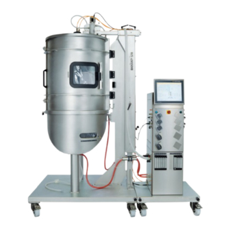
- Page 14 3 Specifications 3.1 Dimensions and Weights On/off switch Fig. 3-1: Dimensions, setup and connection of a BIOSTAT ® STR (in this figure: BIOSTAT ® STR 50, DW) Tower Bag Holder STR 50 STR 200 STR 500 SW and DW SW and DW 1000 DW H –...
- Page 15 3.2 Operating Conditions Ambient Conditions Specification(s) Temperature range 10–40°C Humidity < 85% relative humidity Height above sea level Max. 2000 m Interiors Protection class IP2 Pollution level 2 Overvoltage category II 3.3 Connections and Energy Supply Lines (Defaults) Connection of Connection Values Special Notes Compressed air...
- Page 16 3.4 Manufacturer’s ID Label Every Sartorius device has its own type number (e.g., BB-8803060) and a specific serial number. This serial number is as follows: 00300 / 11 00300: system number / 11: year of production The manufacturer's ID label for the BIOSTAT STR is located on the back of the tower: ®...
- Page 17 4 Design and Function The BIOSTAT ® STR bioreactor range includes process-scale bioreactors that can be used for batch, fed-batch and continuous processes. Main components include: − Bag holders are supply equipment and consist of an open stainless steel frame for holding the STR Bag.
- Page 18 4.1.2 Aeration Depending on the model, air, O and CO can be mixed with aeration rates and strategies consistent with the respective “P&I Diagram” and the “DCU4 Operating Manual.” Aeration is regulated by mass flow controllers, valves and variable area flowmeters.
- Page 19 4.3 Bag Holder The bag holder of the BIOSTAT STR holds the STR Bag and is adapted to the ® respective total volume of the STR Bag. In addition, the bag holder serves as a connector to the control tower. The bag holder is mounted to a rollable carriage.
- Page 20 4.5.2 Peripheral Connections The BIOSTAT ® STR tower allows for a large number of connections to external devices: Detailed information on these peripheral connections can be found in “2. Principles of Operation” in the “DCU4 Operating Manual.” 4.5.3 Software The integrated software features all the functions required for flexible operation: y For example, the display of measurements/process values, calibration routines and/ or controls, depending on their definition in the “Major Components List.”...
- Page 21 5 Transportation, Packaging and Storage The following information summarizes the key aspects to be observed during the transport, packaging and storage. They also apply to the re-installation at the workplace after a change of location or after temporary suspensions from use. 5.1 Safety Instructions for Transportation Risk of personal injury and property damage due to high weight of the bioreactor!
- Page 22 5.4 Storage The disassembled and repackaged bioreactor (which can be broken down into more than one packaging unit) must be stored under the following conditions: − Not outdoors. − Dry and free of dust. − Do not expose to aggressive media. −...
- Page 23 STR Bag. Components that do not correspond to the specifications of Sartorius Stedim Systems GmbH must not be used. y Report the transport damage, missing parts or malfunctions to your responsible Sartorius Stedim Systems GmbH representative and/or Sartorius Stedim Biotech GmbH. 6.1.2 Requirements Relating to Laboratory Connections...
- Page 24 6.2 Setup and Connection BIOSTAT ® STR bioreactors can be set up on every suitable laboratory benchtop. Risk of personal injury and property damage if the installation location does not meet the set requirements. The place of installation must meet the requirements set down in the following Chapter “6.4 Dimensions, Connecting Energy Supply Lines.”...
- Page 25 2. Check to make sure that all laboratory power connections are correctly preinstalled, set and ready-to-operate (as per “3.3 Connection Values and Energy Supply Lines” and/or “P&I Diagram”): – Mains voltage, – Cooling water connection and return flow in the laboratory, –...
- Page 26 AD10 AS10 AD11 AS11 AD12 AD13 AD15 AS16 AD14 AS12 AD16 AS17 AD17 AS18 AS13 AD18 AS14 AD19 AS15 AD20 AS19 AD21 AS20 AD22 AS21 AD23 AS22 AD24 AS23 Fig. 6-2: Connection items on the tower, side “A” STR 200, single wall version) STR 200, double wall version) Tower (example: BIOSTAT ®...
- Page 27 Tower (Example: BIOSTAT STR 200, single wall and double wall version) ® B1: Ethernet host B2: PA B3: mains B4: balance-A2 B5: subs-A2 B6: ext. signals-2 B7: balance-B2 B8: subs-B2 B9: balance-C2 B10: ext. signals-1 B11: subs-A1 B12: balance-A1 B13: balance-C1 B14: subs-B1 B15: balance-B1 Fig.
- Page 28 CS10 CD10 CD11 CS11 CD15 CD16 CD14 CS14 CS16 CD17 CD12 CS12 CS15 CD13 CS13 CS18 CD18 CD19 CS17 CD20 CS19 CS21 CD22 CS20 CD21 Fig. 6-4: Connection items on the tower, side “C” STR 200, single wall version) STR 200, double wall version) Tower (Example: BIOSTAT ®...
- Page 29 6.4 Dimensions, Connecting Energy Supply Lines Danger of functional problems and operational malfunctions or defects through contaminated cooling water or contaminated air and/or gases. Cooling water, compressed air and/or gases must be free of residual corrosion, deposits or the likes, deriving from the laboratory supply lines. If necessary, the suitable prefilters should be installed.
- Page 30 5. Connect the lines for the heating system/temperature control module and cooling in accordance with your configuration (SW/DW). 6. Connect all laboratory supply lines (e.g., gas lines O , air, N and cooling water lines) as per your configuration and the information in “6.4 Dimensions, Connecting Energy Supply Lines.”...
- Page 31 6.6 Using the Probe Holder Ensure that the probe holder described here is suitable for installation in a BIOSTAT ® STR 50 L, BIOSTAT ® STR 200 L, BIOSTAT ® STR 500 L or BIOSTAT ® STR 1000 L. Differences during installation possibly resulting from this are labeled accordingly. Danger of personal injury and property damage! If not used properly, the probe holder of the BIOSTAT STR presents a risk of...
- Page 32 6.6.2 Installing the Probe Holder: Danger of injury to personnel and damage to property! If not installed properly, the probe holder on the BIOSTAT® STR presents a risk of injury to personnel and damage to system components. To avoid damage, only follow the working steps described here! 1.
- Page 33 STR Bag itself, its installation in the bag holder and its functionality. Documents relating to customer-specific equipment will be included with the device or sent to you under separate cover. Please contact Sartorius Stedim Biotech GmbH if you require additional information to go with these.
- Page 34 Only use safety components and equipment that Sartorius Stedim Systems GmbH has approved for use with the BIOSTAT STR as supplied, see “2.1 Intended Use.” ® After installation and connection of bag holder equipment, e.g., for inlet and exhaust air, electrodes, sampling tubing etc., always check that the parts have been secured properly.
- Page 35 max. min. M L K J max. “FT” view E1, E2 min. M L K J “FT” view E1, E2 Schematic structure of a STR Bag Item Function Item Function Headspace aeration Exhaust air (contains pressure sensor Temperature sensor for STR 50/200) Single-use sensor port with DO and pH patches Feed...
- Page 36 STR Bag Specifications The following components of the STR Bag are supplied operational and/or ready-to- connect: 3-blade segment impeller (standard) 6-blade disk impeller (optional) Ring sparger (standard) Micro sparger (optional) Combination sparger (optional) Types, Specifications STR 50 STR 200 STR 500 STR 1000 Working volume [L] 1000...
- Page 37 2. Open the drain port retainer: First pull the safety bolt down. Turn the lever to the right until the drain port retainer is completely open. 3. Prepare the filter holder for the filter: Push all 6 clamps of the filter holder down. 4.
- Page 38 7.1.4.2 Unpacking the STR Bag This chapter describes the correct way to unpack the STR Bag. This unpacking description applies to all STR Bag sizes (STR 50|200|500|1000 Bag). The STR 1000 Bag is unpacked here as an example. Possible differences between the individual bag sizes are emphasized separately. User Information Safety Instructions during Operation Risk of damaging the STR Bag due to improper unpacking.
- Page 39 2. Cut and remove the bands surrounding the box. 3. Lift the lid from the box. 4. Pull away the sides of the box. 5. Remove the transparent bag. Operation...
- Page 40 6. Grasp the four pipes to lift the STR Bag out of the bottom panel of the box. 7. A pictogram is located on the black bag, which explains further unpacking instructions in brief: 8. Carefully use scissors to cut the black bag and the transparent bag underneath and tear open the upper side of both bags.
- Page 41 10. Grasp the four pipes to lift the STR Bag out of the black bag. 11. Remove the drain line from its position at the upper foam piece (on STR 500|1000 Bag a small foam piece must be removed first): 12.
- Page 42 13. Remove the upper foam piece. 14. Pull away the four pipes at the corners of the lower foam piece while a second person holds the STR Bag firm at the drain port. 15. Grasp the STR Bag at the top port and drain port and lift it out of the lower foam piece.
- Page 43 7.1.4.3 Inserting and Inflating the STR Bag Damage to the sparger and STR Bag due to incorrect aeration rates! To avoid damage to the sparger and/or STR Bag, the total aeration rate (the total gas volume flow) must not exceed a value of 0.2 vvm. Furthermore, the following applies: Aerate a single micro sparger with no more than 0.1 vvm.
- Page 44 4. Lift the STR Bag over the double wall and carefully insert it vertically into the drain port retainer of the bag holder. Direct the drain line through the drain port retainer (two people required for STR 50|200; three people required for STR 500|1000). Insert the STR Bag so that the tubing is directed toward the door hinges.
- Page 45 While keeping a firm grasp on the height adjustment lever, loosen the locking lever of the motor arm. Lower the motor arm via the height adjustment lever until the stop. While lowering the motor arm, connect the coupling of the STR bag to the magnetic coupling of the motor.
- Page 46 9. Connect the sparger line as follows: Remove the filter from the packaging. Connect the filter via the OPTA coupling to the sparger line of the STR Bag. For STR 50|200 bag only: Clamp the inlet air filter to the designated point in the filter holder Connect filter and tower using the supplied tubing (see Chapter “7.1.4.4 Installing the Tri-Clamp Connection of a Filter Line”).
- Page 47 Risk of property damage to the bag (overpressure if the process is performed incorrectly). During the entire operation, the inlet air filter for the headspace must be connected with the pressure sensor, the safety valve and this with the tower (overlay).
- Page 48 16b. STR 500|1000 Bag: Continue aeration until the bag film no longer touches the internal parts. Then carry out the overlay aeration process as follows: Stop aeration. Connect the stirrer shaft of the STR Bag to the motor as described in the following: Pull the top port of the stirrer shaft of the STR Bag vertically up until the magnetic coupling snaps into place (two people are required for this action and must work from a higher position).
- Page 49 7.1.4.4 Installing the Tri-Clamp Connection of a Filter Line User Information Safety Instructions during Operation Risk of damage to the STR Bag and mounted components due to improper installation. To avoid the risk of damage and functional/operational faults or defects due to improper installation, carefully follow all of the instructions given here.
- Page 50 4. Set the aeration tube with the tri-clamp connection and nozzle on the tri-clamp seal. 5. Close the tri-clamp clip around the tri-clamp connection between the filter line and the aeration tube. Note that the aeration tube must be connected to the DCU. 7.1.4.5 Additional Process Preparations Before closing the bag holder, make sure that all tubing and external connections are mounted without clamping and are not trapped!
- Page 51 7.1.5.2 Fixing the PT100 Temperature Sensor Only use the PT100 included in the equipment supplied! The use of other temperature sensors may damage the STR Bag. y Required Equipment: PT100 temperature sensor and temperature sensor bracket 1. Open the screw connection of the temperature sensor bracket. 2.
- Page 52 7.1.5.3 Activating the Single-Use Sensor Port and Installing the Fiber Optic Cables Before activating the single-use sensor port, the STR Bag must be installed in the bag holder and fully inflated. Before filling the STR Bag the following steps must be performed: 1.
- Page 53 6. Push the fiber optic cable through the bracket until it protrudes by approximately 4–5 cm. 7. Fix the fiber optic cable by tightening the white head of the bracket. 8. Push the fiber optic cable into the respective opening (pO /DO fiber optic cable into the red opening and pH fiber optic cable into the white opening).
- Page 54 7.1.5.4 Calibrating the Sensors 1. Carry out the calibration in accordance with the “DCU4 Operating Manual” and using the calibration data on the label affixed to the STR Bag. 2. Take a sample (as per Chapter “7.4.3 Removal Through the Sampling Port”) and recalibrate the value for pH offline.
- Page 55 7.1.7 Concluding Process Preparations Immediately prior to starting up the BIOSTAT ® STR ensure that the process preparation steps described in Chapter 6 up to and including 7.1.6 have been carried out: y The mechanical setup described in Chapter “6. Installation and Initial Startup” has been completed.
- Page 56 7.2.1.2 Startup of the Temperature Control Circulation (on DW only) If the pump runs dry, this can damage the temperature control module. Do not switch on the heating mechanism until the temperature control circulation has been filled. For initial startup of the BIOSTAT ®...
- Page 57 7.2.1.4 Motor Control Abruptly stopping the stirrer can damage it. Set the target value for the agitator to switch off initially to “10 rpm”. First set the target value of the stirrer to “10 rpm” and wait until 10 rpm has been reached.
- Page 58 7.4 Notes on Running Processes/Sampling 7.4.1 Sampling Risk of contamination and/or infection! Samples contain living cells. Wear protective gloves and other suitable protective clothing. Disinfect and clean all contaminated objects and surfaces. Laboratory drains and collection vessels must be suited for biological waste water. Observe the safety guidelines for handling sample residues that are critical to safety, e.g., pathogenic cells.
- Page 59 6. Close the tube clamp on the sampling tubing. 7. Turn the syringe counterclockwise, take the syringe from the tubing end and dispose of the syringe in accordance with Chapter “10. Disassembly and Disposal.” The syringe must be neutralized (e.g., through heat sterilization) before it can be properly disposed of.
- Page 60 7.5 Uninstalling a STR Bag Danger of personal injury and property damage! Uninstalling the STR Bag improperly may cause injury and damage the STR Bag itself. This uninstallation description applies to all STR Bag sizes (STR 50|200|500|1000 Bag). The STR 200 Bag is uninstalled here as an example. Possible differences between the individual bag sizes are emphasized separately.
- Page 61 16a. For STR 50|200 Bag, open the tri-clamp connection that connects the STR Bag to the motor: – Loosen the motor arm bracket. – Lift the motor arm and carefully push the STR Bag downward. – Fix the motor arm in the highest position. 16b.
- Page 62 21b. Lift the STR 500|1000 Bag out of the bag holder by holding it at the top and drain port and directing the drain line through the drain port retainer (three people required here): Prepare the STR 50|200|500|1000 Bag for the autoclave process. Place the STR Bag in a suitable autoclave and start the autoclave process: Note the required autoclave size before autoclaving: >...
- Page 63 8 Maintenance As a supplement to the activities described in Chapter “8.3 Concluding Processes, Cleaning and Maintenance,” all maintenance information in the service concept is summarized in this chapter again. 8.1 Safety Information for Maintenance Danger caused by electric current! Contact with voltage-carrying components can be fatal.
- Page 64 The temperature control circuit must be filled with water after reassembly and/or maintenance work has been carried out on the bioreactor. Prior to filling, check that all connections are tightened firmly. After filling, check for any visible leaks. If a leak is discovered, do not start up operation of the temperature control system, but eliminate the cause of the leak.
- Page 65 Pos. Bag holder Action Acceptance Criteria Lock Function test Check for ease of access, tighten screws if necessary Door settings Function test Check that door gap is parallel, if gap deviates by more than 5 mm, contact SSB Service Window seal Function test If window seal is damaged, contact SSB Service Lock Doors...
- Page 66 8.3.2 Cleaning Bag Holder and Tower Danger of corrosion and damage to bag holder and tower. Avoid strongly caustic or alkaline and/or chloride-containing detergents. Cleaning and maintenance intervals mainly depend on the extent of bag holder and tower (especially the display) use and how contaminated they are (by improper use, etc.) y Check whether it is sufficient for your process to use a wet cloth to clean the bag holder (and its components like the motor arm and filter holder, for example) and...
- Page 67 9 Malfunctions The following chapter describes possible causes for malfunctions and measures to correct these problems. In the case of increasingly occurring faults, reduce the maintenance intervals in accordance with the actual load. In the case of disruptions which cannot be rectified using the following information, contact the manufacturer;...
- Page 68 Ser. No. Replacement Part Name Order Number STR filter heater 50|200 L, 230 V BB-8804088 STR filter heater 500|1000 L, 230 V BB-8804089 STR filter heater 50|200 L, 24 V (from serial no. 400/09) BB-8804087 STR filter heater 500|1000 L, 24 V (from serial no. 400/09) BB-8804260 Filter holder, 6x 50|200 L BB-34161196 Filter holder, 6x 500|1000 L...
- Page 69 10 Disassembly and Disposal Once the lifespan of the system has come to an end, the system must be disassembled and disposed of in an environmentally friendly way. 10.1 Safety Information for Disassembly and Disposal Danger of injury due to personnel being insufficiently qualified! Disassembling the bioreactor without being sufficiently qualified could be fatal.
- Page 70 10.3 Disposal/Decontamination Declaration Attention must be paid to the applicable laws, rules and regulations, when disposing of the contaminated components. The packaging is made from environmentally-friendly materials that can be used as secondary raw materials. Packaging that is no longer needed can be disposed of in Germany free of charge via the VfW dual system (contract number D-59101-2009- 1129).
- Page 71 EC / EU Declaration of Conformity...
- Page 72 11 Index Accessories . . . . . . . . . . . . . . . . . . . . . . . . . . . . . . . . . . . . . . . . . 50 Operating conditions .
- Page 73 Appendix A Additional Process Information/ Instructions A1. Leak Test (for STR Bag) This chapter describes the correct procedure for the STR Bag leak test. This test description applies to all STR Bag sizes (STR 50|200|500|1000 Bag). Possible differences between the individual bag sizes are emphasized separately. A1.1 User Information A1.1.1 Intended Use The leak test (for STR Bag) described here must only be conducted by trained and...
- Page 74 Required Equipment for STR 50|200|500|1000 Bag: Pressure outlet tube, item no.: 26288---BT3D Required Equipment for STR 50|200 Bag: “Bag tester fleece F” (front side) “Bag tester fleece B” (back side, same side as the door hinges) “Bag tester fleece T” (top) Appendix A –...
- Page 75 Required Equipment for STR 500|1000 Bag: “Bag tester fleece F” (front side) “Bag tester fleece B” (back side, same side as the door hinges) “Bag tester fleece T” (top) Appendix A – A1 Laek-Test (for STR Bag)
- Page 76 A1.2 Installing the “Bag Tester Fleece” To install the “bag tester fleece”, proceed as follows: STR 50|200 Bag STR 500|1000 Bag 1. Insert the “bag tester fleece F” (opposite the door hinges). 2. Insert the “bag tester fleece B” (same side as the door hinges). 3.
- Page 77 STR 50|200 Bag STR 500|1000 Bag 5. Once the top port is connected to the motor magnet, place the “bag tester fleece T” around the STR Bag. 6. Close one door. 7. Place the loops over the doors. Appendix A – A1 Laek-Test (for STR Bag)
- Page 78 STR 50|200 Bag STR 500|1000 Bag 8. Close the second door and direct the loops through the lower ring on the bag holder. Then close the loops with the Velcro ® fasteners. 9. Inflate the STR Bag and position the STR Bag so that it is facing the right way (as per the “BIOSTAT ®...
- Page 79 STR 50|200 Bag STR 500|1000 Bag 2. Attach the pressure outlet tube to the overlay filter capsule. 3. Connect all clamps except the overlay clamp. Incorrect test result due to insufficient test setup. Ensure before carrying out the leak test that all clamps are closed, except the overlay clamp.
- Page 80 STR 50|200 Bag STR 500|1000 Bag 7. Remove the pressure outlet tube from the overlay filter capsule. 8. Attach the overlay aeration tube to the overlay filter capsule. Appendix A – A1 Laek-Test (for STR Bag)
- Page 81 1.4 Uninstalling the “Bag Tester Fleece” Uninstalling the “bag tester fleece” is recommended. If the “bag tester fleece” remains in the bag holder, the heating and cooling performance is reduced. This may affect the temperature control during your cultivation process. STR 50|200 Bag STR 500|1000 Bag 1.
- Page 82 STR 50|200 Bag STR 500|1000 Bag 3. Loosen the protective cover at the screws on both sensor windows. 4a. STR 50|200 Bag: Remove the “bag tester fleece F.” 4b. STR 500|1000 Bag: Remove the “bag tester fleece F” on the side. 5a.
- Page 83 A2. Single-Use Exhaust Cooler This chapter describes the correct installation of the single-use (disposable) exhaust cooler on a STR Bag. This installation description applies to all system sizes (BIOSTAT ® STR 50|200|500|1000). Possible differences between the individual system sizes are emphasized separately. A2.1 User Information A2.1.1 Safety Instructions during Operation Risk of damage to the single-use exhaust cooler due to improper installation.
- Page 84 2.2 Installing the Devices Use the following tool for installation depending on the size of the system: − STR 50|200 Bag = 5 mm Allen wrench (see Chapter 13.2.1) − STR 500|1000 Bag = 6 mm Allen wrench (see Chapter 13.2.2) 2.2.1 Installation on STR 50|200 Bag 1.
- Page 85 3. Unscrew both rear screws on the opposite side of the motor arm using the 5 mm Allen wrench. 4. Place the holder for the condensation return pump on the motor arm and tighten both screws with the 5 mm Allen wrench. 2.2.2 Installation on STR 500|1000 Bag 1.
- Page 86 3. To this end the lever on the hinge is pressed in and loosened. 4. Turn the holder for the single-use exhaust cooler to the right until it stops. 5. Press the lever on the hinge and tighten it. Note the different installation angles of the holder depending on the size of your BIOSTAT ®...
- Page 87 3. Connect the devices as follows: Connection Point A Single-use exhaust cooler (cooling water “outlet”) B Single-use exhaust cooler (cooling water “inlet”) C Unichiller 006 (cooling water “outlet”) D Unichiller 006 (cooling water “inlet”) E Return from single-use exhaust cooler (Unichiller 006/cooling water inlet) F Supply to single-use exhaust cooler (Unichiller 006/cooling water outlet) Screw the installation kit on the Unichiller 006 using a 19 mm wrench.
- Page 88 Single-use exhaust cooler DS200L---EC DS001K---EC single-use exhaust cooler single-use exhaust cooler STR 50|200 Bag STR 500|1000 Bag Exhaust tube, inlet, OPTA 1/2” ID silicone tube, 1/2” female 3/4” ID silicone tube, 3/4” female Exhaust tube, outlet, OPTA 1/2” ID silicone tube, 1/2” male 3/4”...
- Page 89 4. Open the primary bag of the single-use exhaust cooler carefully using scissors and remove the single-use exhaust cooler. 5. Pull on the handle of the holder for the single-use exhaust cooler to loosen it. 6. Insert the single-use exhaust cooler from the left. 7.
- Page 90 2.3.3 Connecting the Single-Use Exhaust Cooler 1. Connect the exhaust line of the STR Bag and the exhaust “inlet” of the single-use exhaust cooler using an OPTA connector. 2. Connect the exhaust filter and the exhaust “outlet” of the single-use exhaust cooler using an OPTA connector.
- Page 91 8. Connect the quick coupling of the single-use exhaust cooler (cooling water “outlet”) of the installation kit to the cooling water “outlet” of the single-use exhaust cooler. 2.3.4 Starting Up the Single-Use Exhaust Cooler Damage to the single-use exhaust cooler when using water that does not comply with specifications.
- Page 92 7. Start the condensation return pump. 8. Open the EXHCOND menu in the main menu of the touch display on the tower. 9. Set 5%. 10. Press “auto.” 11. Press “ok.” 2.3.5 Uninstalling the Single-Use Exhaust Cooler 1. Stop the condensation return pump. 2.
- Page 93 5. Switch off the pump for the Unichiller 006 (see “Unichiller 006 Operating Instructions”). 6. Switch off the Unichiller 006 (see “Unichiller 006 Operating Instructions”). Risk of water pouring out when single-use exhaust cooler is uninstalled. To avoid potential associated risks, place a container under the overflow of the Unichiller 006 when uninstalling the cooler to catch any water that may pour out.
- Page 94 10. On the BIOSTAT STR 500|1000 the angle of the holder for the single-use exhaust ® cooler must be adjusted. – To this end the lever on the hinge is pressed in and loosened. – Turn the holder for the single-use exhaust cooler in the vertical position. –...
- Page 95 14. Pull on the handle of the holder for the single-use exhaust cooler. 15. Remove the single-use exhaust cooler on the left. 16. The single-use exhaust cooler is autoclaved together with the STR Bag. 17. If necessary, dispose of the single-use exhaust cooler (as per the “BIOSTAT STR Operating Instructions,”...
- Page 96 Sartorius Stedim Biotech GmbH August-Spindler-Strasse 11 37079 Goettingen, Germany Phone: +49.551.308.0 Fax: +49.551.308.3289 www.sartorius.com The information and figures contained in these instructions correspond to the version date specified below. Sartorius reserves the right to make changes to the technology, features, specifications and design of the equipment without notice.
Need help?
Do you have a question about the BIOSTAT STR and is the answer not in the manual?
Questions and answers