
Related Manuals for Sartorius Stedim Biotech BIOSTAT B


Summary of Contents for Sartorius Stedim Biotech BIOSTAT B
- Page 1 185013007862 Operating Manual ® BIOSTAT Fermenter | Bioreactor 85037-545-02 Vers. 05 | 2014 *** TeDIS Valid on Date Printed Printed on: 20-09-2023 11:08:41 ***...
- Page 2 PDF file in various international languages. If the CD is missing, you can obtain a copy form us by specifying the order number: Order number: 85037-545-13 Sartorius Stedim Biotech GmbH Technical Editorial Department August-Spindler-Strasse 11 37079 Goettingen, Germany tech.pubs@sartorius-stedim.com...
-
Page 3: Table Of Contents
Contents 1. About this Document ............1.1 Validity . - Page 4 4. Software ................4.1 User Information .
- Page 5 8.4 Filling the Culture Vessel with Culture Medium ......® ® 8.4.1 UniVessel Glass / UniVessel .
- Page 6 8.11 “Controller” Menu ............8.11.1 Functional Principle and Equipment .
- Page 7 9. Faults ................9.1 Safety Instructions .
-
Page 8: About This Document
1. About this Document All information and instructions in this operating manual have been compiled in consideration of applicable standards and guidelines, the state of technology and our many years of experience and knowledge. These operating instructions provide you with all the information necessary to install ®... -
Page 9: Validity
If the documents supplied do not match the equipment delivered to you or if any documents are missing, please contact the person responsible for your area or get in touch with Sartorius Stedim Biotech directly. About this Document *** TeDIS Valid on Date Printed... -
Page 10: Symbols Used
1.3 Symbols Used As a means of instruction and direct warning against hazards, all text statements to be particularly noted in these operating instructions will be marked as follows: This instruction denotes a possible danger with medium risk that death or severe injury may result if it is not avoided. -
Page 11: Safety Instructions
2. Safety Instructions Failure to observe the following safety precautions can have severe consequences: − Danger to personnel due to electrical, mechanical or chemical influences − Failure of important functions of the unit Read the safety precautions and dangers listed in this section thoroughly before starting the unit. -
Page 12: Informal Safety Measures
2.2 Informal Safety Measures − Always keep the operating manual in the location where the unit is in use. − In addition to the operating manual, follow all general and local regulations for accident prevention and environmental protection. 2.3 Symbols Used on the Unit The following symbols are used on the device: Especially hazardous area or hazardous use of the peristaltic pump! Follow the instructions in the accompanying documents. -
Page 13: Intended Use And Foreseeable Misuse
2.4 Intended Use and Foreseeable Misuse The operational safety of the unit is only ensured when it is used for its intended purpose and operated by trained personnel. The device is used for the cultivation of prokaryotic and eukaryotic cells solely in aqueous solution. -
Page 14: Residual Risks From Use Of The Unit
− Never open the device. The device may be opened only by authorized personnel of the Sartorius Stedim Biotech Company. − Work on the electrical equipment of the device may only be carried out by Sartorius Stedim Service or authorized technicians. -
Page 15: Danger Due To Components Under Pressure
2.7 Danger Due to Components Under Pressure Danger of injury from leaked substances! If individual components are damaged, gaseous and liquid materials may escape under high pressure and e.g. cause injury to eyes. Therefore: − Do not start the culture vessel without a safety valve or comparable overpressure safety (e.g. -
Page 16: Danger Due To Nitrogen
Reactions with other substances! − Ensure that pure oxygen does not come into contact with oil or grease. − Use only materials and substances suitable for use with pure oxygen. 2.9.2 Danger Due to Nitrogen Danger of suffocation due to escaping nitrogen! Escaping gas at high concentrations may force the air out of closed rooms and can cause loss of consciousness, leading to suffocation. -
Page 17: Danger Due To Hot Surfaces
Danger of injury from escaping feed and culture media! − Use the specified hoses only. − Use hose fastenings on connecting pieces. − Empty the feed hoses before loosening the hose connection. − Wear personnel protective clothing. − Wear safety glasses. Danger of contamination from escaping feed and culture media! −... -
Page 18: Safety And Protective Systems
2.14 Safety and Protective Systems 2.14.1 Main Switch The main switch is on the operator side of the control unit. The main switch is simultaneously the emergency-off switch used to turn the unit on and off. 2.14.2 Safety Valves and Pressure Reducer Danger of injury from bursting culture vessels and lines! −... -
Page 19: Personal Protective Equipment
The overheating protection within the unit limits the maximum permissible temperature for the temperature control system. The following temperature control systems can be used: − Temperature control system water circulation system − Temperature control system heating jacket 2.15 Personal Protective Equipment When operating the unit, personal protective equipment must be worn in order to minimize dangers to health. -
Page 20: Emergency Instructions
2.16 Emergency Instructions Preventive Measures − Always be prepared for accidents or fire. − Keep first aid equipment (bandages, blankets, etc.) and fire extinguishers handy. − Familiarize personnel with accident reporting, first aid, fire extinguishing and rescue facilities. − Keep entry and rescue routes free for rescue vehicles and rescue personnel. Measures to be Taken After Accidents −... -
Page 21: Personnel Requirements
− The operator must also ensure that all employees are familiar with the basic regulations concerning workplace safety and accident prevention, trained in handling the unit and have read and understood the operating manual. − Furthermore, the operator must evaluate the safety-conscious work of personnel at regular intervals and demonstrate training of personnel and notification of danger. -
Page 22: Personnel Responsibilities
Technician Due to his or her technical education, knowledge and experience, as well as knowledge of applicable regulations, a technician is capable of carrying out tasks assigned to him or her and independently detecting and avoiding possible dangers. Electrician Due to his or her technical education, knowledge and experience, as well as knowledge of applicable standards and regulations, an electrician is capable of carrying out work on electrical equipment and independently detecting and avoiding possible dangers. -
Page 23: Training And Instruction
2.18.5 Training and Instruction Personnel must regularly receive instruction from the operator. Log the performance of this training for better tracking. Date Name Type of training Training given by Signature Safety Instructions 23 23 *** TeDIS Valid on Date Printed Printed on: 20-09-2023 11:08:41 ***... -
Page 24: Device Overview
3. Device Overview ® ® The devices BIOSTAT B-MO, BIOSTAT B-CC are designed for the cultivation of microorganisms and cells in discontinuous and continuous processes. They were designed for cultivating microorganisms and cells at various reactor volumes. The devices can be used to conduct studies on developing and optimizing fermentation procedures and to perform limited-volume production fermentation processes in a reproducible way. -
Page 25: Control/Supply Units
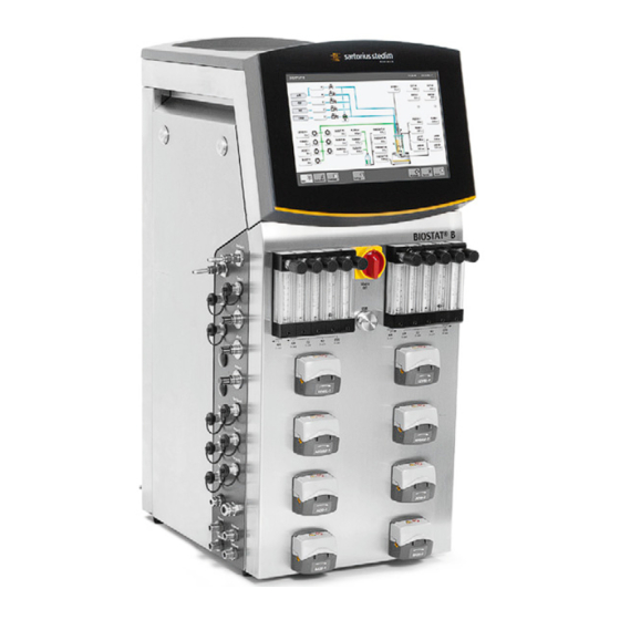
3.1 Control/Supply Units ® 3.1.1 BIOSTAT B-MO Single / Twin ® ® Fig. 3-1: Example of the BIOSTAT B-MO Twin with UniVessel Glass ® 3.1.2 BIOSTAT B-CC Single / Twin ® ® Fig. 3-2: Example of the BIOSTAT B-CC Twin with UniVessel Glass Device Overview 25 25... - Page 26 Variants with different culture vessels ® ® ® ® UniVessel Glass – UniVessel Glass UniVessel SU – UniVessel ® RM Rocker 20 | 50 – RM Rocker 20 | 50 UniVessel Glass – RM Rocker 20 | 50 ® ® ®...
-
Page 27: Control Elements And Connections
3.1.3 Control Elements and Connections ® Fig. 3-3: Front view / detail view BIOSTAT B-CC Twin Pos. Description ® ® BIOSTAT B-CC (MO) Twin BIOSTAT B-CC Twin with UniVessel ® Glass / UniVessel ® with RM Rocker 20 | 50 Operator display (touch panel) Operator display (touch panel) Main switch / power switch... - Page 28 ® Fig. 3-4: Back view / detail view BIOSTAT B-CC Twin Pos. Description Power connection / Potential equalization Potential equalization (if available in lab) Power connection Network port Common alarm connection Tempering medium inlet d 10 mm, laboratory side connection Tempering medium return d 10 mm, laboratory side connection Aeration (laboratory side connection) ®...
- Page 29 ® Fig. 3-5: Side view / detail view BIOSTAT B-CC, ® ® UniVessel Glass, UniVessel Pos. Description Comments Aeration ® Overlay (BIOSTAT B-CC)* Serto gland d 6 mm Sparger Serto-screw d 6 mm Sensors Temp Temperature sensor, M12 plug connection Serial-A Scales connection (FWEIGHT), RS-232, M12 plug connection pH/Redox-A...
- Page 30 Fig. 3-6: Side view / detail view BIOSTAT ® Pos. Description Comments Aeration ® Overlay (BIOSTAT B-CC) Serto gland d 6 mm Sensors pH-A Opt. Optical pH-sensor, VP8 plug Serial-A Scales connection (FWEIGHT), RS-232, M12 plug connection Scales connection (FWEIGHT), Serial-B RS-232, M12 plug connection pO2-A Opt.
-
Page 31: Aeration Modules
3.1.4 Aeration Modules The supply units of the devices can be equipped with a range of different aeration modules. Every device can only be equipped with one of the aeration modules described below. The laboratory gas supplies for each of the gases must be preset to 1.5 barg (21.76 psig). The pressure in the vessel supply lines is limited to max. -
Page 32: Modules "Additive Flow 4-Gas
Connections supply unit: ® BIOSTAT B-MO Single: “Sparger-1” ® BIOSTAT B-MO Twin: “Sparger-1, -2” ® Fig. 3-8: BIOSTAT B-MO connections ® 3.1.4.2 Modules “Additive Flow 4-Gas” (BIOSTAT B-CC Single / Twin) Module “Additive Flow 4-Gas” when an RM Rocker 20 | 50 is connected. Module ®... -
Page 33: Peristaltic Pumps
3.1.5 Peristaltic Pumps The peristaltic pump units WM 114 are located on the supply unit and convey the correction media and nutrient media through hoses into the vessel. ® Up to 4 peristaltic pump modules can be installed on the BIOSTAT B Single. -
Page 34: Culture Vessels
3.2 Culture Vessels In the following figures, the functional elements will be displayed using examples of ® ® the UniVessel Glass 1 L and UniVessel SU 2 L (made of pre-sterilized polycarbonate). More information about the culture vessels (single-walled, jacketed, volumes) can be ®... -
Page 35: Univessel ® Su
® 3.2.2 UniVessel ® Fig. 3-13: Functional elements, UniVessel SU 2 L with holder Pos. Description Stirrer with connecting pieces for motor adapter of different control units Cover plate with ports/retainers for sensors, supply media, sampling, aeration, exhaust air Plastic vessel (temperature control by heating jacket or heating/cooling jacket) Holder Device Overview 35 35... -
Page 36: Rm Rocker 20 | 50
3.2.3 RM Rocker 20 | 50 Fig. 3-14: Functional elements, RM Rocker 20 | 50 with CultiBag RM Pos. Description Hood CultiBag RM Bag holder Supply and control unit (RM Rocker 20 | 50) Touch panel Connections, left side Device Overview *** TeDIS Valid on Date Printed Printed on: 20-09-2023 11:08:41 ***... -
Page 37: Stirrer Driver
3.3 Stirrer Driver Fig. 3-15: Stirrer driver Pos. Description Stirrer driver for culture vessel coupling Power supply Sleeve The top drive includes a direct drive for the stirrer shaft and a magnetic coupling. Available drive motors: − Motor 200 W, rpm range 20 ... 2000 1/min Rpm Ranges The standard stirrer shaft is sealed with a rotating mechanical seal. -
Page 38: Software
4. Software 4.1 User Information This operating manual shows the standard functions of the DCU software. DCU systems can be customized according to the customer’s specifications. Therefore, this documentation may describe functions that a delivered configuration does not contain or a system may contain functions that are not described here. Information about the actual scope of functionality can be found in the configuration documents. - Page 39 For interruptions in operation, the startup behavior of outputs and system functions that have a direct effect on the associated end unit (regulators, timers, etc.) depend on the type and duration of the interruption. There are several different types of interruptions: −...
-
Page 40: Principles Of Operation
4.3 Principles of Operation 4.3.1 Device-specific User Interfaces The user interfaces of the DCU are variable, depending on the device version and culture vessel type. The following versions are possible: − BIOSTAT ® B-MO Single UniVessel ® Glass ® ® −... -
Page 41: Work Area
4.3.2.2 Work Area Fig. 4-2: Example BIOSTAT ® B-CC Twin: Menu “Main” for the Unit “1” (above illustration) and for Unit “1” and Unit “2” (middle/lower illustrations) Software 41 41 *** TeDIS Valid on Date Printed Printed on: 20-09-2023 11:08:41 ***... -
Page 42: Footer
The measuring range shows the function elements and submenus of the active main function: − Preselected process values with current measured or set value − Pumps or dispenser counters with process values, e.g. flow rates or dispensing volumes for correction materials and gases −... - Page 43 Display: − Selected main function: Button light gray, activated − Function not selected: Button dark gray, deactivated ® Depending on the configuration, the BIOSTAT B can be equipped with one or two culture vessels. Operation is specific for any culture vessel: −...
-
Page 44: Display
4.3.3 Display The display of function elements is shown in the following table: Symbol Display Meaning, use Function element [PV tag]: Field for short name (“tag”) for the function element, e.g. TEMP, STIRR, pH, pO , ACID, SUBS, BALANCE Button with gray underline MV [Unit]: Field for measured or set value in its physical unit −... -
Page 45: Overview Of The Main Function Keys
Examples for function elements, short descriptions, measured values, working values and submenus that can be called by selecting touch buttons [ see Chapter “8.8 “Main” Menu“ and Chapter “4.3.6 Direct Function Keys for Selection of Submenus“]. 4.3.4 Overview of the Main Function Keys Button, symbol Meaning, use Main function “Main”... -
Page 46: Overview Of Selection Keys
4.3.5 Overview of Selection Keys Button Meaning, use Cancel Changes will not be saved Confirmation of input Further controller parameters Cancel Changes will not be saved Deleting characters Selection of sign when entering a value Selection list of process values 4.3.6 Direct Function Keys for Selection of Submenus The function elements in the work area of the “Main”... - Page 47 In this section, an example of screens and submenus accessible via direct function keys is shown. Detailed instructions for the associated functions and possible inputs can be found in the Chapters “8.10 “Calibration” Menu“ and “8.11 “Controller” Menu“. Example: Input of Temperature Setpoint Fig.
- Page 48 Fig. 4-4: Set value input and selection of the “TEMP” controller mode from the “Controller” menu When the “Controller” menu is accessed, the “Setpoint” touch key can be used to enter a set value (after pressing the touch key, a screen keyboard also opens). The touch button “off”...
-
Page 49: Selection Lists And Tables
4.3.7 Selection Lists and Tables If submenus contain lists of elements, short names or parameters that cannot be displayed in a window, a scrollbar with a position marker is displayed: Fig. 4-5: Access to values accessible from the submenu after assignment of a channel in the trend display. To page through lists that contain more entries than can be displayed in the window, the following options are available: Press the arrow keys “... -
Page 50: Password Protection Of Individual Functions
4.4 Password Protection of Individual Functions Only disclose this information to authorized users or service staff. If required, remove this page from the manual and keep it in a special place. Certain system functions and settings that should only be accessible for authorized personnel are protected by a password. -
Page 51: Transport
5. Transport The device will be delivered by the customer service of Sartorius Stedim Systems GmbH or by a transport company engaged by Sartorius Stedim Systems GmbH. 5.1 Inspection Upon Acceptance by the Recipient 5.1.1 Report and Document Transport Damage Upon acceptance of the unit by the customer, the unit must be inspected for visible transport damage. -
Page 52: Instructions For Transport Within The Company
5.3 Instructions for Transport Within the Company When moving the device, it is particularly important to do so in such a way as to prevent damages by force or careless loading and unloading. Danger of severe personal injury and property damage due to improper transport! −... -
Page 53: Setup
6. Setup The guide for setup of the device is the setup drawing. The setup of the device is to take place according to contractual conditions, − by Sartorius Stedim Service, − by Sartorius authorized specialist personnel, − by the customer’s authorized specialist personnel. Setting up the bioreactor involves the following main steps: −... -
Page 54: Work Surfaces And Loads
6.3 Work Surfaces and Loads The device is designed as a bench-top system and should be set up on a stable laboratory table. The work surface must be big enough for the equipment required for the fermentation process. It must be easy to clean and, where relevant, to disinfect. - Page 55 ® ® Example setup for UniVessel Glass, UniVessel ® Fig. 6-1: Example setup for BIOSTAT B-CC Twin / Single Pos. Description ® Control unit, BIOSTAT B-CC Twin UniVessel ® Glass (2 L, jacketed) ® UniVessel SU (2 L, Single Use) ®...
- Page 56 Equipment for emergency shutdown and shut-off devices, e.g., for the power supply, water or gas feed, as well as the particular equipment connections, must be kept clear and easily accessible. Set Up Dimensions The required lab table dimensions and distances of the culture vessels to the device are shown in the installation plans [ Chapter “15.3 Setup Drawings“].
-
Page 57: Laboratory Energy Sources
6.4 Laboratory Energy Sources The connections for energy and supply systems must be prepared before installation of the device in the work area. They must be easily accessible, correctly installed, set in accordance with the device’s specifications and ready to operate. Risk of death from energy that is unexpectedly released, such as electric shocks! Energy supply lines may be incorrectly dimensioned and not protected against impermissible fluctuations and faults. -
Page 58: Manufacturer's Id Label
− The power cables must have the correct plugs that match your laboratory AC outlet. Do not use any damaged mains cables, e.g. with broken insulation, and in particular if the wires are exposed. − Do not attempt to repair any defective power cables or replace incorrect plugs. For this purpose, please be sure to contact a qualified service provider or technical customer service at Sartorius Stedim Systems GmbH. -
Page 59: Tempering Medium
− Faults resulting from contaminants or corrosion residues. Malfunctions and damages arising from unsuitable water quality are excluded from the warranty granted by Sartorius Stedim Biotech. Green microbes inside the double wall are a sign of algae formation caused by organic contaminants in the water. -
Page 60: Gas Supply
6.4.4 Gas Supply Gas supply comprises the following gases (depending on the integrated aeration module): Aeration Modules ® ® BIOSTAT B-MO BIOSTAT B-CC / RM Rocker 20 | 50 “Additive Flow 5-Gas” “Additive Flow 2-Gas” “Additive Flow 4-Gas” AIR (air) AIR (air) Oxygen (O Oxygen (O... - Page 61 − Make sure that the supply gases are dry and free of dirt, oil and ammonia. − Install suitable filters, if necessary. − Malfunctions and damages arising from contaminated gas media are excluded from the warranty granted by Sartorius Stedim Biotech. Setup 61 61...
-
Page 62: Startup
7. Startup Starting up the bioreactor involves the following main steps: − Connecting of the device to the power supply “7.2 Connecting the Device to the Power Supply“] − Connecting the laboratory’s water supply “7.3 Connecting Laboratory Water Supply to the Device“] −... -
Page 63: Connecting The Device To The Power Supply
7.2 Connecting the Device to the Power Supply The connections for the power supply (2) and the potential equalization (1) can be found on the rear of the device. Mains Connection − The device can be supplied in the following voltage versions: −... -
Page 64: Connecting Laboratory Water Supply To The Device
7.3 Connecting Laboratory Water Supply to the Device Risk of injury due to bursting culture vessel! If the pressure in the temperature control circuit is too high, there is a risk that the double-walled versions of the culture vessels will burst. Therefore: −... -
Page 65: Connecting Laboratory Gas Supply To The Device
7.4 Connecting Laboratory Gas Supply to the Device The gases | compressed air supplied inside the laboratory must correspond to the supply unit’s specifications. The connections for the gas supply are located at the back of the supply media unit [ Fig. -
Page 66: Connecting The Stirrer Driver (Only Univessel Glass / Univessel Su)
7.5 Connecting the Stirrer Driver ® ® (only UniVessel Glass / UniVessel Risk of injury when motor is running! The motor can be started up for testing purposes before being fitted by switching on the DCU system. Reaching into the running drive can cause injuries to the fingers. −... -
Page 67: Connecting The Univessel
® 7.6 Connecting the UniVessel SU Holder ® ® The UniVessel SU holder is for mounting the UniVessel SU culture vessel and | or to compile and analyze measurement signals from the optical pH and DO sensors in the ® UniVessel SU culture vessel. -
Page 68: Connect Rm Rocker 20 | 50 For Cultibag Rm
® ® Further information on the UniVessel SU, UniVessel SU Holder, adapter ring and barcode scanner can be found in the following operating instructions: ® − “UniVessel SU culture vessel installation instructions” ® − “UniVessel SU Holder operating instructions” − “Adapter ring installation instructions” 7.8 Connect RM Rocker 20 | 50 for CultiBag RM Connect “D-LINK 2”... -
Page 69: Connecting The Temperature Control
7.11 Connecting the Temperature Control 7.11.1 Jacketed Culture Vessels / Single-walled Culture Vessels with Heating | ® ® Cooling Jacket (only UniVessel Glass / UniVessel Danger of injury from shattered glass! Excess pressure can cause the glass culture vessels to break. Bursting glass culture vessels can cause cuts and damages to the eyes. - Page 70 Fig. 7-8: Hose kit | temperature control for jacketed culture vessels Fig. 7-9: Hose kit | temperature control for single-walled culture vessels with heating | cooling jacket Pos. Description Culture vessel, jacketed Heating | cooling jacket Hose with plug-in sleeve Sealing coupling Hose with sealing coupling for return (length 600 mm) Supply unit connection (return)
-
Page 71: Cultibag Rm Temperature Control
Fill Tempering Medium The device is switched on [ Chapter “7.13 Turning the Device On and Off“]. Connect the inlet hose (7) to supply unit connection (6) and then to connection (9). Connect the return hose to supply unit connection (5) and then to connection (2). Switch on the device. -
Page 72: Heating Jacket
® ® 7.11.3 Heating Jacket (only UniVessel Glass / UniVessel The heating jackets are designed for heating single-walled culture vessels. Danger to life caused by electric shock if heating blanket is defective! The heating blankets have to be in perfect condition. −... -
Page 73: Connecting The Exhaust Cooling Hoses (Only Univessel Glass)
® 7.12 Connecting the Exhaust Cooling Hoses (only UniVessel Glass) Fig. 7-13: Hose kit, exhaust cooling for culture vessels Pos. Description Exhaust cooler Hose with sealing coupling for return Supply unit connection (return) Supply unit connection (supply line) Hose with sealing clip for inlet Connecting Hoses to the Supply Unit Connect the supply hose (5) to the supply unit connection (4). -
Page 74: Turning The Device On And Off
7.13 Turning the Device On and Off Prerequisites The system must be properly installed and connected in accordance with the specifications. You must also have gained familiarity with the safety instructions Chapter “2. Safety Instructions“]. Ensure that all required supply energies are connected. Switching On ®... -
Page 75: Preparing And Running The Process
8. Preparing and Running the Process Read the operating manual carefully before carrying out processes on the unit. This is especially important for the safety instructions [ Chapter “2. Safety Instructions“]. 8.1 Overview Process preparation of the bioreactor during the relevant process involves the following main steps, depending on the culture vessels used: ®... -
Page 76: Connecting Transfer Lines
Measures Required Before Installing and Connecting Certain Parts − pH sensor (see operating instructions of the manufacturer): − Calibrate the pH sensor before autoclaving the culture vessel. − Calibrate the zero point and slope of the sensors using the buffers in accordance with the scheduled measuring range. - Page 77 Fitting the Transfer Lines Risk of chemical burns from acids and bases! If the hoses are not securely fastened, there is risk that they will slide off, in which case the correction media will leak out. − Wear personal protective equipment: −...
-
Page 78: Filling The Culture Vessel With Culture Medium
8.4 Filling the Culture Vessel with Culture Medium ® ® 8.4.1 UniVessel Glass / UniVessel Heat-Resistant Culture Medium Before autoclaving, fill the culture medium into the culture vessel via the lid port. Non-Heat-Resistant Culture Medium Fill the culture vessel with a small amount of water (approx. 200 - 300 ml) and autoclave the culture vessel. -
Page 79: Preparing The Cultivation Process
To ensure reliable sterilization (e.g., to kill off thermophilic spores), the temperature in the culture vessels must be maintained at sterilization temperature for at least 30 minutes. 8.6 Preparing the Cultivation Process Danger of burns due to hot surfaces! The premature removal of culture vessels from the autoclave can cause burns. −... -
Page 80: Mounting The Agitator Drive
Exhaust Cooling Connect the supply and return tubing of the exhaust cooling to the ports of the exhaust cooler at the culture vessel. Exhaust Heater – UniVessel ® SU (Single Use): Fit the exhaust filter heater to one of the exhaust filters and connect the plug to the mains supply [ installation instructions “Heater for Exhaust Filter”]. - Page 81 ® Assembly of UniVessel Glass Culture Vessels Fig. 8-2: UniVessel ® Glass stirrer coupling Prior to placing the device, take the motor (1) and connect the coupling with the sleeve (2) to the stirrer shaft. Gently twist the motor housing to the left or right until the motor’s coupling and the coupling (3) on the stirrer shaft engage.
-
Page 82: Heating | Cooling Jacket Installation
Fit the adapter (1) to the coupling of the stirrer shaft (2) “Motor adapter installation instructions”]. Prior to placing the device, take the motor (3) and connect the coupling with the sleeve (4) to the adapter. Gently twist the motor housing to the left or right until the motor’s coupling and the coupling on the adapter engage. -
Page 83: Installing The Heating Blanket
Fitting the Heating | Cooling Jacket to the Culture Vessel The heating | cooling jacket is filled with tempering medium and connected to the temperature control system hoses [ Chapter “7.11.1 Jacketed Culture Vessels / ® Single-walled Culture Vessels with Heating | Cooling Jacket (only UniVessel Glass / ®... - Page 84 Operating the Heating Jacket Danger of burns at the heating jacket! Depending on the operating temperature intended for the culture vessel, the heating jacket can heat up to approx. 80°C. − When in operation (above 40 °C), never touch the heating jacket with your bare hands.
-
Page 85: Connecting The Aeration Modules
8.6.4 Connecting the Aeration Modules 8.6.4.1 Conducting Preliminary Steps The culture vessels must be fitted with the equipment needed for medium aeration UniVessel ® Glass operating manual]: − Aeration pipe with ring sparger or microsparger or an aeration basket with a silicon tube membrane, −... -
Page 86: Connecting The "Additive Flow 2-Gas" Aeration System
The safety valve station is interconnected between bioreactor control unit and culture vessel. This prevents inadmissible overpressure in the culture vessel. Set up the safety valve station on a stable foundation in proximity to the bioreactor control unit. Set up the safety valve station such that the front (1) is facing you. Connect the hoses on the outputs Overlay and Sparger with the inputs of the safety valve station (2) and (3) [ safety valve station installation instructions]. -
Page 87: Connecting The "Additive Flow 4-Gas" Aeration System
8.6.4.4 Connecting the “Additive Flow 4-gas” Aeration System Connect the tubing from the outlet “Sparger” (1) to the supply air filter of the culture vessel. Aerate the culture medium with nitrogen and calibrate the zero point Chapter “8.10 “Calibration” Menu“]. Aerate the culture medium with air and calibrate the slope. -
Page 88: Preparing The Corrective Solution Supply
8.6.5 Preparing the Corrective Solution Supply The supply unit is fitted with up to 8 integrated peristaltic pumps WM 114 for supplying correction media (acid, base, anti-foam agents or nutrient solutions/ substrates). Preliminary Steps: The culture vessels must be fitted with the following equipment needed for supplying correction media or media removal [UniVessel ®... - Page 89 Changing Position of the Tube Holder Changing to smaller hose diameter: Prior to changing the tube holder position, turn off the pump. In order to re-position the lower tube holders on both sides of the pump head, use a pointed object (e.g. a ballpoint pen).
-
Page 90: Performing A Process
8.7 Performing a Process Danger of injury from shattered glass! The culture vessel can burst due to unallowed overpressurization, resulting in cuts and injury to the eyes inflicted by glass splinters. − Only operate the temperature control circuit of double-walled culture vessels at ambient pressure. -
Page 91: Setting Up The Measurement And Control System
Danger of chemical burns from acids and bases! Excess acids and alkalines in correction media bottles can cause chemical burns in the event of uncontrolled leakage! − In order to neutralize the acids and alkalines, empty the lines into appropriate containers. -
Page 92: Guaranteeing Sterility
8.7.2 Guaranteeing Sterility Sterility Test Before starting the fermentation process, it is possible to perform a sterility test. The sterility test can be used to establish whether the culture vessels and the connected equipment have been safely sterilized or are contaminated. Enter all of the process parameters as specified (temperature, speed, aeration, pH regulation, etc.). -
Page 93: Main" Menu
8.8 “Main” Menu 8.8.1 General Information The “Main” menu opens after the control unit has been switched on. This is the central starting point for in-process operation. Example with glass culture vessels: Fig. 8-12: Start screen Twin variant “Main All” menu. Fig. -
Page 94: Process Displays In The "Main" Menu
8.8.2 Process Displays in the “Main” Menu The function elements can display associated process values: − Values measured by connected probes such as pH, pO , foam, etc. − Calculated variables like pump filling amounts, calculated values of arithmetic functions, etc. −... - Page 95 − Mode selection for agitator speed “STIRR-#” − Mode selection for level control “LEVEL-#” − Analogous for foam monitoring “FOAM-#” − “LEVEL #” pump control mode selection (automatic and manual pump control) Fig. 8-14: Menu screens for functions accessible directly from the “Main” menu Preparing and Running the Process 95 95...
-
Page 96: Trend" Menu
8.9 “Trend” Menu 8.9.1 “Trend” Display Using the “Trend” display, the user can graphically display process values for a period of up to 72 hours. This overview of the process flow gives for example a quick impression as to whether the process is running as expected or whether irregularities or disruptions are present. -
Page 97: Configuring The "Trend" Display
8.9.2 Configuring the “Trend” Display 8.9.2.1 Setting the Trend Display for Parameters Select the “Trend” menu button. Press the key of the channel that you want to set: The “Channel # Settings” window opens. Fig. 8-16: Menu for parameter selection and setting To change the parameter for the channel, press “PV”. -
Page 98: Resetting The Display Range
8.9.2.3 Resetting the Display Range Press “Reset Range” on the “Channel # Settings” screen to reset a modified display range back to the factory setting for “Max” and “Min”. Fig. 8-19: Resetting a running trend recording 8.9.2.4 Setting the Trend Display Color The color for every parameter can be selected from a table. -
Page 99: Calibration" Menu
8.10 “Calibration” Menu 8.10.1 General Information In the “Calibration” menu, all calibration actions required for routine operation can be activated: − Calibration routines for sensors: e.g. pH, pO − Calibration of pump filling counter: e.g. acid, base, substrate − Calibration of gas filling counter: e.g. N , CO Fig. -
Page 100: Calibration Ph-#" Submenu
The effects of heat during sterilization and reactions of the diaphragm and/or electrolytes with components of the medium can influence the measurement properties of the pH sensors. Test and calibrate the pH sensors before each use. − Whenever possible, use buffer solutions manufactured by the sensor manufacturer as contained in the equipment supplied with the pH sensor. -
Page 101: Perform Calibration
Press the touch button “Measure” in the submenu “Calibration pH-#”. The submenu “Calibration pH-# Mode” opens: 8.10.2.3 Perform Calibration Depending on your choice, only the zero point (Calibrate Zero) or the slope (Calibrate Slope) is calibrated, or a full calibration (Calibrate) is carried out. Select/enter Temperature Compensation Press the touch button “Calibrate”... -
Page 102: Direct Input Of The Zero Offset And Slope
Slope Calibration Hold the pH sensor in the second buffer solution. In the input window “pH-#: Slope Buffer”, input the pH value of the second buffer solution. Observe the measured value display in the window “pH-#: Slope Value”. Once the display is stable, confirm the measurement with “OK”: The pH sensor is calibrated. -
Page 103: Do Calibration (Conventional Sensor)
8.10.3 DO Calibration (conventional sensor) 8.10.3.1 General Information on the pO Sensors Calibration of the pO sensor is based on a two-point calibration. Measurement is performed in [% oxygen saturation]. Calibration determines the sensor parameters zero current (“zero”) and slope (“slope“). The reference parameter for “zero” is the oxygen-free medium in the culture vessel. -
Page 104: Perform Calibration
Press the touch button “Measure” in the submenu “Calibration pO2-#”. The submenu “Calibration pO2-# Mode” opens: 8.10.3.3 Perform Calibration Depending on your choice, only the zero point (Calibrate Zero) or the slope (Calibrate Slope) is calibrated, or a full calibration (Calibrate) is carried out. The pO sensor must be serviced if: −... -
Page 105: Direct Input Of The Zero Offset And Slope
In the input window “pO2-#: Slope Value”, input the measured value for the slope. 8.10.4 Optical pH and pO Sensors Sartorius Stedim Biotech’s optical sensor technology makes it possible to measure the pH and dissolved oxygen (DO) values non-invasively. The sensors are integrated ®... -
Page 106: Signal Quality Of The Optical Probes
8.10.4.1 Signal Quality of the Optical Probes CultiBag RM bags are equipped with optical pH and DO disposable probes. An optical fiber is used for the sensor connection. The sensor is located at the end of a hose, in the interior of the bag. The fiber-optic cable transmits light at a specific wavelength from the measurement amplifier to the sensor and the sensor’s luminescent response back to the measurement amplifier. -
Page 107: Notes On Calibration
8.10.4.2 Notes on Calibration The indicator strip for the measured value sensors decays when exposed to light. The measured value drifts by approx. 0.13 pH based on 10,000 measurements. To compensate for this drift, enhanced DCU configurations provide a “recalibration” function. -
Page 108: Calibration Ph-#" Submenu
8.10.5.1 “Calibration pH-#” Submenu Field Value Function, entry required Mode Display of the active operating mode: Measuring, Calibrating, Recalibrating − Inactive [Inactive] Appears after commissioning, before the first calibration − Calibrate [Calibrate] Appears when going through the calibration steps − Measure [Measure] Indicates that the measurement is active in process... -
Page 109: Enter Initial Calibration Data
8.10.5.2 Enter Initial Calibration Data ® The calibration data to be entered are printed on the CultiBag or UniVessel SU used. These data must be entered, as no (valid) pH measurement is possible beforehand. ® (When using the UniVessel SU, the calibration data can be scanned with the barcode scanner). -
Page 110: Performing Recalibration
Transferring the Parameters The data are transferred to the DCU system. Wait until the parameters have been transferred. The initial calibration of the pH sensor is now complete. Take a sample and recalibrate the pH sensor in case of deviations. 8.10.5.3 Performing Recalibration Press the button “Inactive”... -
Page 111: Configuring The Measurement Cycle For Ph Measurement
8.10.5.4 Configuring the Measurement Cycle for pH Measurement Optical pH sensors show decay of the indicator dyes, e.g. photo-bleaching. This degradation depends on the amount of light and increases with the pH value (for alkaline media). The pH sensors used in the CultiBag RM are designed for 20,000 measurement points. Calculation of the Measurement Cycle The measurement cycle can be configured so that 20,000 measurements are possible over the total process time. -
Page 112: Submenu "Calibration Po2
8.10.6.1 Submenu “Calibration pO2-#” Field Value Function, entry required Mode Display of the active operating mode: Measuring, Calibrating, Recalibrating − Inactive [Inactive] Appears after commissioning, before the first calibration − Calibrate [Calibrate] Appears when going through the calibration steps − Measure [Measure] Indicates that the measurement is active in process −... -
Page 113: Perform Initial Calibration
8.10.6.2 Perform Initial Calibration ® The calibration data to be entered are printed on the CultiBag or UniVessel SU used. These data must be entered, as no (valid) DO measurement is possible beforehand. ® (When using the UniVessel SU, the calibration data can be scanned with the barcode scanner). -
Page 114: Performing Recalibration
Transferring Parameters The data are transferred to the DCU system. Wait until the parameters have been transferred. The initial calibration of the DO sensor is now complete. 8.10.6.3 Performing Recalibration Press the button “Inactive” to bring up the window “Mode Calibration pH #”. Press the touch button “Re-Calibrate“... -
Page 115: Totalizer For Pumps And Valves
Modification of the Measurement Cycle In the submenu “Calibration pO2-B#”, press the touch button “Samp. Rate” to modify the measurement cycle. Enter the standard password “19” and confirm with [ok]. Change the value for the pO measurement cycle according to the above calculation. - Page 116 Preparing for Pump Calibration Always use the same type of tubing with the same dimensions for calibrating and pumping the media. To calibrate, it is recommended that a suitable scale be used, as this is more accurate. Prior to calibration, the hose must first be filled. To do this, proceed as follows: Insert the hose into the pump.
-
Page 117: Scale Taring
Press the touch button “Flow” in the submenu “Calibration LEVELT-#”. In the input window “LEVELT-#: Flow”, enter the feed rate and confirm with “OK”. Resetting the Filling Counter Press the touch button “Reset” in the submenu “LEVELT-# Mode”. The filling counter is reset. Activating the Filling Counter The filling counter is reset after calibration. - Page 118 Zero-taring on the example scale/culture vessel Press the touch button “tare” for zero-taring in the submenu “VWEIGHT-# Mode”. The display “Tare” (measured value in the DCU system) is set to zero. The gross weight “Gross” (measured value of the scale) remains unchanged. Tare Correction during Running Operations Press the touch button “Hold”...
-
Page 119: Controller" Menu
8.11 “Controller” Menu 8.11.1 Functional Principle and Equipment The control loops in the DCU system work as PID controllers, setpoint generators or two-point controllers and are adapted to their control circuits. PID controllers can be parameterized to match the control task. The controller outputs control their control elements either continuously or using pulse-width modulation. -
Page 120: Controller Selection
Controllers Function Module “Additive Flow 5-Gas” ® ® UniVessel Glass / UniVessel Slave controller or setpoint generator for gas proportioning valves, pulsed feed: − AIROV-#, AIRSP-# − Air for headspace aeration (Overlay) and medium aeration (Sparger) − O2OV-#, O2SP-# − O2 for headspace aeration (Overlay) and medium aeration (Sparger) −... -
Page 121: General Controller Operation
8.11.3 General Controller Operation For the most part, operation of the controller is uniform. It comprises setting the setpoints and alarm limits and the selection of the control operating mode. If a controller can control more than one output, the controller output is assigned by means of the parameterization functions accessible with a password. -
Page 122: Setpoint Profile
8.11.4 Setpoint Profile Controller Profile The “Profile Parameter” function can be used to navigate to the setpoints of the individual controllers. Time-based setpoint profiles can be set up. Up to 20 steps can be configured. Any pre-installed DCU system can be additionally retrofitted with control functions by changing the configuration. -
Page 123: General Controller Parameterization
Field Value Function, entry required Elapsed Time h:m:s Display of the elapsed time since the profile start in [hours:minutes:seconds] Graphical display of the elapsed time on the profile screen 1-20 Number of the profile spike Time h:m:s Input of the time for the profile spike Setpoint [PV] Input of the setpoint for the profile spike in the physical... -
Page 124: Output Limits
As a general rule, it is not required to change the control parameters. The exceptions are controlled loop paths, the behavior of which is strongly influenced by the process, e.g. pH and DO (pO ) control loops. 8.11.5.1 Output Limits You can limit the controller output for the target value generator and PID controller downwards (MIN) and upwards (MAX). -
Page 125: Pid Parameters
8.11.5.4 PID Parameters The PID controllers can be optimized using the PID parameters XP, TI and TD. The implemented digital controllers run according to the position control algorithm. They allow structural toggles (P, PI, PD, PID) and changing the parameters during ongoing operations. - Page 126 Master Controller TEMP Operator Screen Fig. 8-27: Master Controller TEMP-1 Operator Screen Refer to Chapter “8.11.3 General Controller Operation“for notes on the fields, entered values and entries. Operation Observe the maximum permissible temperatures of the component groups and fixtures your bioreactor is equipped with. Culture vessel Maximum permissible temperatures for “TEMP”...
-
Page 127: Temperature Measurement Without Slave Controller (Temp)
Special notes − In “auto” mode of the “TEMP-#” master controller, the “JTEMP-#” slave controller automatically switches to “cascade” mode. In the “off” setting of the master controller, the slave controller is also automatically “off”. − On certain systems, a setpoint limit must be parameterized for the slave controller using the “MAX”... -
Page 128: Speed Regulation (Stirr)
8.11.8 Speed Regulation (STIRR) Function The speed controller works like a target value generator for an external motor controller, which controls the speed of the stirrer motor. In addition to its function as a single controller, the speed controller can also be used as a slave controller in pO control. -
Page 129: Antifoam Controller "Foam
8.11.9 Antifoam Controller “FOAM” Function The autoclavable foam sensor is installed in the culture vessel. The sensor is adjustable in height, so that the sensor tip can be adjusted to the maximum level of the medium. A threshold signal generated by the foam sensor and amplified by a measurement amplifier serves as the input signal of the foam regulator “Controller FOAM-#”. -
Page 130: Level Control With Level Sensor (Level)
8.11.10 Level Control with Level Sensor (LEVEL) Function The autoclavable level sensor is installed in the culture vessel. The sensor is adjustable in height, so that the sensor tip can be adjusted to the maximum level of the medium. A threshold signal generated by the level sensor and amplified by a measurement amplifier serves as the input signal of the level regulator “Controller LEVEL-#”. -
Page 131: Gravimetric Level Control (Vweight)
8.11.11 Gravimetric Level Control (VWEIGHT) Function With gravimetric leveling, a particular medium volume can be kept in the culture vessel. The pump speed is controlled automatically by the weight change in the culture vessel. Adding: Here you can define a minimum setpoint. As soon as the weight of the culture vessel is lower than this reference value, a variable speed (analog) addition pump is activated by the control equipment. -
Page 132: Gravimetric Filling Pump Controller "Flow
8.11.12 Gravimetric Filling Pump Controller “FLOW” Function The controller “FLOW-#” is a precise gravimetric filling pump controller. It is used a weighing system and an analog filling pump. Because the control algorithm in the DCU system works directly with the weight measured on the scale/balance, the gravimetric filling controller allows accurate proportioning over days and weeks. -
Page 133: Filling Pump Controller (Subs)
8.11.13 Filling Pump Controller (SUBS) Function To introduce nutrient solution, the filling pump controller can control an internal or external pump. The controller function works as a setpoint generator, handles control, and emits an analog setpoint signal for the pump. Controller operator screen Fig. -
Page 134: Gas Controller (Gas Filling Controller / Gas Flow Controller)
8.11.14 Gas Controller (Gas Filling Controller / Gas Flow Controller) Gas controllers control gas supply for the corresponding gas segment, e.g. “AirOV-#”, “AirSp-#”, “O2SP-#”, “N2SP-#”, “CO2OV-#”, or “CO2Sp-#” and introduce gases into the aeration segments “Overlay” or “Sparger”. The following types of gas controllers can be used: −... -
Page 135: Ph Controller
Follow the instructions regarding the “Parameter Settings in the System” in the “Configuration Documentation”. − MIN/MAX output limits are entered in % of the control range of the gas feed. When entering values directly in the OUT field, take the measurement range for the aeration rate into consideration. -
Page 136: Parameter Settings
8.11.15.3 Parameter Settings A DEADB dead zone can be entered in the pH controller parameterization screen. The controller remains inactive as long as the measured value remains within the dead zone around the setpoint. Example: Set dead zone: ± 0.05 pH Set target value: 6.0 pH In that case, the control loop is inactivated at nominal values between 5.95 pH and... -
Page 137: Do Control Methods
8.11.16 DO Control Methods The DCU system features various methods of DO control. Which of them is possible, required or sensible for the controlled terminal unit depends on the configuration or process. − When aerating with air, either the oxygen portion can be reduced by adding nitrogen or the air can be enriched with oxygen. -
Page 138: Po Controller Cascade (Cascade Controller)
8.11.16.1 pO Controller CASCADE (cascade controller) Operator Screen Fig. 8-31: pO cascade controller menu on the “Controller – All” operator screen Refer to Chapter “8.11.3 General Controller Operation“ for notes on the fields, entered values and entries. The operator screen also include the following input fields: Field Value Function, display, entry required... - Page 139 DO Cascade Controller Parameterization Screen Fig. 8-32: Example: Configuration of the operator screen Field Value Function, display, entry required DEADB Entry of the deadband Cascade # [Controllers] Slave controller with the relevant parameters Minimum output limit, corresponding to the minimum target value for the slave controller.
- Page 140 Operation of the Multi-stage Cascade Controller Select the slave controller according to the desired priority in the “Cascade Parameter pO2-#” submenu. Set each minimum and maximum controller setpoint limit for the selected slave controller using the output limits MIN or MAX in the parameterization image of the pO2 controller.
-
Page 141: Po Controller Advanced (Polygon Controller)
8.11.16.2 pO Controller ADVANCED (polygon controller) The advanced DO controller monitors and regulates the DO in the bioreactor or the controlled end unit for which the DCU system was designed. The “pO2 controller ADVANCED” is optional and available alternative to the “pO2 controller CASCADE”. - Page 142 Settings for the Advanced DO Controller Operating Display and Input Window for the Master Controller Field Value Function, display, entry required Mode Controller switched off, output on stand-by [ configuration] auto Controller active, controls the actuator if necessary Manual Manual access to controller output DO (pO Display of the DO Setpoint...
- Page 143 Parameterization of the DO Master Controller Fig. 8-34: Parameterization of the DO Master Controller Elements of the Parameterization Screens Field Value Function, display, entry required Current controller output “Out”, in % of maximum control range Minimum output, 0 to 100% of the control range Maximum output, 0 to 100% of the control range DEADB [PV]...
- Page 144 Setting the “P”, “I”, or “D” Controller Parameters: The adaptation of PID controllers requires knowledge of control theory. The setting options listed here are rough guidelines. Only qualified personnel should carry out controller optimization. Depending on the process (e.g. stability of gas intake or actuator), it may be necessary to change the parameters “P”, “I”, or “D”...
- Page 145 Fig. 8-36: Configuring the slave controller Elements of the Operator Screens for Selection and Configuration Field Value Function, display, entry required Cascade # Slave controller to be assigned to the “Cascade #” position; up to 6 slave controllers are possible configuration, specification] Up to five slave controllers can form a polygon controller.
- Page 146 Configuration of Slave Controllers Activate the function key of the slave controller you want to configure, e.g. “AIR-SP1”. Enter the password. Access is password-protected in order to prevent unauthorized changes [ see Chapter “4.4 Password Protection of Individual Functions“, Page 50]. In the “Setpoint”...
-
Page 147: Aeration Strategies
Set “STIRR-#” between “Out” = 0 to 40 % and increase to a maximum at 60 %. Leave “Out” constant for 60 to 100 %. Leave “SUBS-A” constant in the range “Out” = 0 to 60 % and increase to a maximum at 80 %. - Page 148 ® Aeration Strategy “Exclusive Flow” (N , air, O for BIOSTAT B-CC) The aeration strategy “Exclusive Flow” behaves like the aeration strategy “O Enrich- ment”. In addition, oxygen can be removed from the culture medium by adding nitrogen. Select “N2SP-1”, “AIRSP-1” and “O2SP-1” as slave controllers. The starting point of the polygon controller in this aeration strategy is located at “Out”...
- Page 149 ® Aeration Strategy “Gasflow Ratio” (air, O for BIOSTAT B-MO) In the aeration strategy “Gas Flow Ratio”, a constant amount of gases is supplied to the culture vessel. Select “AIRSP-1” and “O2SP” as slave controllers. For “AIRSP-1“, set − a maximum setpoint for “Out” = 0 % −...
-
Page 150: Rm Rocker 20 | 50 Controller Functions
8.11.17 RM Rocker 20 | 50 Controller Functions In this section, the special controller functions angle control, aeration rate, sensor signal quality and additional features of the RM Rocker 20 | 50 in the version “Optical” are described. Fig. 8-40: Main screen “Controller” of a configuration with RM Rocker 20 50 and CultiBag RM Additional Functional Elements, RM Rocker 20 | 50 Symbol... -
Page 151: Angle Control
Signal Quality of the Optical Sensors Display of the raw sensor data in the menu “Calibration” for evaluation of the signal quality of the optical sensors. 8.11.17.2 Angle Control This bioreactor has electronic angle control (“ANGLE”) Angle control ® Fig. 8-42: Main menu of the BIOSTAT Configuration of the process value “ANGLE”... -
Page 152: Position Settings "Positioning
Press the parameter key to view the graphic controller output. Pressing the parameter button again opens a password entry screen. Fig. 8-44: Representation of the “Angle” controller outputs Set the controller parameterization and confirm the entry with “OK”. The submenu window closes. The setpoint is active and is displayed. 8.11.17.3 Position Settings “POSITIONING”... - Page 153 Fig. 8-45: Function “POSITIONING” Configuration of the position: In the work area of the “Controller“ menu, press [ Fig. 8-45] the function key “ANGLE” The menu “POSITIONING” is displayed in the upper right of the screen. Press the touch button “FRONT-#” (or “BACK-#”, “HEAT_PID-#”, “SAMPLING-#”). Example The screen shows the phase “FRONT-#”.
-
Page 154: Aeration Rate
The phase window “Phase FRONT-#” opens. Confirm the start of the phase by pressing the touch button “YES”. The platform of the RM Rocker 20 | 50 now moves to the forward position, the status changes to “Running”. The operation of the phases “BACK-#”, “HEAT_PID-#”, and “SAMPLING-#” is analogous to the described phase “FRONT-#”. -
Page 155: Additional Information
8.11.17.5 Additional Information Functions via RM Rocker 20 | 50 Touch Panel Please observe that the following operations can be made solely on the RM Rocker 20 | 50 Touch Panel: − All calibration work on the RM Rocker 20 | 50 −... -
Page 156: Settings" Menu
8.12 “Settings” Menu The “Settings” menu permits changes to the system configuration. Malfunctions that have unforeseeable impacts on safe operation can result from settings that are not permissible or are unsuited for a certain terminal unit. Settings that impact safe operation are password-protected. Only trained and experienced persons may change these settings. - Page 157 Functions Available for Selection Touch button Function System parameters Changing general system settings see Chapter „8.12.2 Settings“] PV Ranges Configuring measurement ranges of process values see Chapter „8.12.3 Measuring Range Settings“] Manual Operation Switch process inputs and outputs to manual operation [ see Chapter „8.12.4 Manual Operation“] External...
-
Page 158: Settings
8.12.2 Settings Using the “System Parameters” touch button, you can change general system settings, for example setting the real-time clock on the DCU system. To open the “System parameters” submenu, you will need to enter the standard password [ see Chapter “4.4 Password Protection of Individual Functions“] . Field Value Function, entry required... - Page 159 Operator screens − After pressing the “PV ranges” touch button and entry of the standard password, the “Process Value Ranges” submenu opens: Fig. 8-49: Table of process values (or ranges) configured − By pressing the “Ch.” (Channel) touch button, the process values (ranges) can be configured: Fig.
-
Page 160: Manual Operation
8.12.4 Manual Operation When starting up operations and troubleshooting, all analog and digital process inputs and outputs as well as DCU internal parameters can be switched to manual operation (“Manual Operation” touch button). − To open the “Manual Operation” submenu, you will need to enter the standard password [ see Chapter “4.4 Password Protection of Individual Functions“] . -
Page 161: Manual Operation For Digital Inputs
8.12.4.1 Manual Operation for Digital Inputs − For manual operation, disconnect the digital input from the external sensor, e.g. limit value sensors and simulate the input signal from the “ON” or “OFF” input. Operator Screen Fig. 8-51: Manual configuration of digital inputs, example “HEATC-1” (simulation for signal of the power-on status of the heating) Field Value... - Page 162 After working on the manual level, you have to switch all inputs back to the “AUTO” operating mode. Otherwise, the function of the DCU system will be limited. − During manual operation, disconnect the digital output from the internal DCU function and manipulate it directly.
- Page 163 Operator Screen Fig. 8-52: Manual configuration of digital outputs, example “HEAT-1” (simulation for signal controlling the heating) Field Value Function, entry required Description Display of digital input Port Description Hardware address Switch status of the digital output off = turned off nn % on = turned on % = power-on ratio (0 …...
- Page 164 Special notes − The following signal levels apply to the switch status (status): 0 V … 24 V for process outputs (DO) − On pulse-width modulated digital outputs, the relative power-on time is displayed and | or preset. The cycle time is defined in the specific configuration. Example: Cycle time 10 sec, PWM* output 40%:...
-
Page 165: Manual Operation For Analog Inputs
8.12.4.2 Manual Operation for Analog Inputs You can disconnect all analog inputs from the external circuitry during manual operation, e.g., a measurement amplifier and simulate them by entering a relative signal level (0...100%). Operator Screen Fig. 8-53: Manual configuration of analog inputs, example “JTEMP-1” (simulation for input signal for temperature measurement in heating circuit) Field Value... -
Page 166: Manual Operation Of Analog Outputs
8.12.4.3 Manual Operation of Analog Outputs You can disconnect analog outputs from the internal DCU functions and influence them directly using signals with a relative level (0 to 100 %). Output signals have the following priorities: Highest priority Shutdown Manual Operation (Manual Level) Locking Lowest priority Controllers, etc. - Page 167 Special notes − The physical signal level of the analog outputs (AO) can be configured between: − 0 to 10 V (0 to 100%) − 0 to 20 mA (0 to 100%) − 4 to 20 mA (0 to 100%) After working on the manual level, you have to switch all outputs back to the “AUTO”...
-
Page 168: Manual Operation For Controllers ("Control Loops")
8.12.4.4 Manual Operation for Controllers (“Control Loops”) You can simulate controllers in manual operation by entering a setpoint. Operator Screen Fig. 8-55: Manual configuration of controller, example “TEMP-1” (simulation of control signal of temperature controller) Field Value Function, entry required Description Display of the controller, e.g. -
Page 169: Manual Operation Of Sequence Control ("Phases")
8.12.5 Manual Operation of Sequence Control (“Phases”) You can simulate sequences in manual operation (e.g. during startup or in case of problems in the sequence execution during sterilization) by starting a sequence. Operator Screen Fig. 8-56: Manual start of a sequence, example “FILL1” (simulation of control signal for double wall filling) Field Value Function, entry required... -
Page 170: Externally Connected Devices
Special Notes Type and number of sequence steps of individual sequences depends on the configuration of your system. After working on the manual level, you must stop all sequences. Otherwise, the function of the DCU system will be limited. 8.12.6 Externally Connected Devices The “External”... -
Page 171: Service And Diagnosis
Field Value Function, entry required Description Display of the connection, e.g. SERIAL-A1 Interface Description Display of interface Alarm Display and configuration of alarm status: enabled = activate alarm disabled = deactivate alarm Status Display of status of connected device (offline | online) 8.12.7 Service and Diagnosis This operating level is only accessible for interventions by authorized service technicians or associates of Sartorius Stedim GmbH. -
Page 172: Faults
9. Faults 9.1 Safety Instructions Danger to life caused by electrical voltage! Contact with parts under voltage represents a direct danger of death. − Work on the electrical equipment of the device may only be carried out by a competent electrician. −... -
Page 173: Hardware-Related Faults
9.3 Hardware-related Faults Danger of injury if personnel qualifications are insufficient! Improper use can lead to significant personal injury and/or property damage. It is therefore important that all troubleshooting activities be carried out by technical personnel. 9.3.1 Fault Table “Contamination” We recommend that you perform a sterility test before each process. -
Page 174: Troubleshooting Table "Counter Cooling System
Contamination Possible causes Corrective measures During the process, Seals on the culture If possible, continue process to gradually vessel or the integrated the end. Once finished, dismantle components are the vessel and carefully check the defective (e.g. hairline integrated parts. cracks or porosity) If suspected to be damaged (rough, porous surfaces or dents),... -
Page 175: Process-Related Faults / Alarms
9.4 Process-related Faults / Alarms Faults in the operating sequence are displayed as alarms on the operator terminal. To correct these process-related faults, read the following sections. The DCU system makes a distinction between alarms and messages. Alarms have higher priority and are displayed first ahead of the messages. 9.4.1 Alarm Triggering When alarms are triggered, they automatically are displayed in a window that... -
Page 176: Alarm Overview" Menu
9.4.2 “Alarm Overview” Menu The alarm overview can be selected as follows: Press the “Alarm” function key. Operator screen “Alarm” Fig. 9-2: Alarm table, accessible through the “Alarm” function key Field Function, entry required ACK ALL Acknowledges all activated alarms Acknowledges the selected alarm Resets and deletes the selected alarm 9.4.3... - Page 177 “Process value alarms” operator screen Fig. 9-3: Submenu for configuring alarm monitoring, example “TEMP-1”, called from the “Controller” menu, overview “All” Field Value Function, entry required High limit °C Upper alarm limit in the physical unit of the PV Low limit °C Upper alarm limit in the physical unit of the PV Alarm...
- Page 178 Operating Instructions Alarms are displayed on the operator screen and must be acknowledged: − If the value falls outside the alarm limits, an alarm window opens above the active screen. An acoustic signal sounds. The alarm display is displayed in the header line of the operator screen.
-
Page 179: Alarms For Digital Inputs
9.4.4 Alarms for Digital Inputs Digital inputs can be prompted in response to alarm conditions as well. These can be used to monitor components like limit contacts (antifoam | level sensors), motor protection switches or circuit breakers. When an alarm is triggered, an alarm message with the time of the alarm event and an acoustic confirmation signal is emitted. -
Page 180: Alarms, Meaning And Corrective Measures
Operating Instructions A new alarm is indicated in two ways: − When an alarm is triggered for the first time, a message appears in the display and an acoustic signal is emitted. − The alarm symbol is displayed in the header line of the operator screen. Eliminate the cause of the alarm. -
Page 181: System Alarms
9.4.5.2 System Alarms The alarms in the following table are system-generated messages that the user cannot switch off: Text in the alarm line Meaning Remedy Source: Factory Reset Confirmation message for a system reset Confirm alarm with “ACK' started from the “Settings” menu [Name] Watchdog Timeout Confirmation message for a Watchdog Time- Note down the alarm and report it to the... -
Page 182: Cleaning And Maintenance
− Never open the device. The device may be opened only by authorized personnel of the Sartorius Stedim Biotech Company. − Work on the electrical equipment of the device may only be carried out by Sartorius Stedim Service or authorized technicians. -
Page 183: Cleaning
Danger from projecting components! − Ensure that danger points such as corners, edges and projecting components are covered. Preliminary Steps Always take the following preliminary steps when performing cleaning and maintenance: Turn the device off at the main switch. Remove the power supply from the laboratory connection. Turn off all supply media in the lab (water and gas supply). -
Page 184: Cleaning The Culture Vessels
10.1.2 Cleaning the Culture Vessels ® In some cases, it may be sufficient to carefully rinse the culture vessels (UniVessel Glass) with water. If the bioreactor is not used for a while, always fill the culture vessels with water, as this will protect the integrated sensors from drying out. Thorough cleaning is required if components of the culture or media adhere to the inside surfaces of the culture vessels and components installed. - Page 185 Possible Damage Danger to life caused by electric shock if heating jackets are defective! None of the parts should be porous, folded, kinked or chipped. The silicone foil should not be discolored. This is a sign of short circuiting due to broken heating coils or a defective power cord.
-
Page 186: Maintenance
10.2 Maintenance 10.2.1 Carry out Maintenance Work on Function Elements Maintenance performed by the user is restricted to the following tasks: − Maintaining the pH, pO or Redox sensor as per the manufacturer's | supplier's specifications. − Checking and replacing parts subject to wear as well as disposables, e.g., glass vessels, filters, tubing and seals with identical components with the same specifications [ Spare parts list]. -
Page 187: Maintenance Intervals
10.2.3 Maintenance Intervals The cyclical maintenance of the device depends on its service life. The following table lists the maintenance intervals as they are assigned to the components: Before every process After 10-20 autoclave cycles If unsterile Component Activity 1 + yearly Glass culture vessel Pressure hold test Leak test... - Page 188 Before every process After 10-20 autoclave cycles If unsterile Component Activity 1 + yearly Sensor cap (optical O probe) Calibration, visual inspection Foam probe for damage Calibration, visual inspection Level probe for damage Calibration, visual inspection Temperature sensors for damage Plugs, contacts, lines Visual inspection Maintenance according to...
-
Page 189: Storage
11. Storage If the device is not set up immediately after delivery or temporarily not used, it must be stored under the conditions listed in the Chapter “13.1 Ambient Conditions“. Only store the device in dry buildings and do not leave the device outdoors. In case of improper storage, no liability will be assumed for resulting damage. -
Page 190: Disposal
– not even by small commercial operators. For disposal in Germany and in the other member nations of the European Economic Area (EEA), please contact our local service technicians or our Service Center in Goettingen, Germany: Sartorius Stedim Biotech GmbH August-Spindler-Strasse 11 D-37079 Goettingen Phone +49.551.308.0... -
Page 191: Decontamination Declaration
Corrosion When using corrosive gases, the fittings must be chosen accordingly, (e.g. made of stainless steel instead of brass). To change such fittings, please contact Sartorius Stedim Service. We do not accept any responsibility for operating faults and defects resulting from the use of unsuitable gases. -
Page 192: Disposing Of The Unit
12.5 Disposing of the Unit Danger of severe injury due to ejected or falling parts! When disassembling the unit, pay particular attention to those components that contain parts under mechanical tension that could spring out during scrapping, leading to injury. There is also danger due to moving parts and falling objects. −... -
Page 193: Specifications
13. Specifications ® Name: − BIOSTAT B-MO (microbial) ® − BIOSTAT B-CC (cell culture = cell culture) Laboratory Energy Sources Power connection for a 230 V (± 10%), 50Hz, power consumption 10 A supply unit: 120 V (± 10%), 60 Hz, power consumption 12 A Protection class: IP 20 Cooling water supply: Supply rate: min. - Page 194 Weights [kg] Supply unit: approx. 55 (depending on the equipment) ® BIOSTAT Culture vessels: ® UniVessel Glass 1 L DW/SW approx. 10 ® UniVessel Glass 2 L DW/SW approx. 14 UniVessel ® Glass 5 L DW/SW approx. 20 UniVessel ® Glass 10 L DW/SW approx.
-
Page 195: Ambient Conditions
13.1 Ambient Conditions Ambient Conditions Installation location: Conventional laboratory rooms, max. 2,000 m above sea level Ambient temperatures 5 – 40 of between [°C]: Relative humidity [%]: <80% for temperatures up to 31 °C (87.8°F), decreasing linearly < 50% at 40 °C (104°F) Impurities: Pollution degree 2 (Normally only non-conductive pollution occurs. -
Page 196: Conformity & Licenses
14. Conformity & Licenses 14.1 EC Declaration of Conformity With the attached declaration of conformity [ Page 197], Sartorius Stedim ® ® Systems GmbH confirms the compliance of the devices BIOSTAT B-MO and BIOSTAT B-CC with the directives cited. 14.2 GNU Licensing DCU systems contain software subject to the license terms of the “GNU General Public License (GPL)”... - Page 197 Conformity & Licenses *** TeDIS Valid on Date Printed Printed on: 20-09-2023 11:08:41 ***...
-
Page 198: Appendix
15. Appendix 15.1 Service Center Repairs can be carried out on-site by authorized service personnel or by the responsible Service representative of Sartorius Stedim Systems GmbH. The model designation can be found on the model plate or signage [ see Chapter “6.4.2 Manufacturer’s ID Label“]. - Page 199 Sartorius Stedim Systems GmbH to your local service representative or directly to Service Department Sartorius Stedim Biotech GmbH. Robert-Bosch-Str. 5 – 7 D-34302 Guxhagen Germany © 2012 Sartorius Stedim Biotech GmbH Appendix *** TeDIS Valid on Date Printed Printed on: 20-09-2023 11:08:41 ***...
-
Page 200: Setup Drawings
15.3 Setup Drawings On the following pages, you will find setup drawings for the following configurations: − BIOSTAT ® B, Single with UniVessel ® Glass, DW ® − BIOSTAT B, Single with RM Rocker 20 | 50 ® ® − BIOSTAT B, Single with UniVessel SU, SW ®... - Page 201 1200 1622 1496 1496 1882 Appendix *** TeDIS Valid on Date Printed Printed on: 20-09-2023 11:08:41 ***...
- Page 202 1632 1504 1882 Appendix *** TeDIS Valid on Date Printed Printed on: 20-09-2023 11:08:41 ***...
- Page 203 1200 1622 1492 1882 Appendix *** TeDIS Valid on Date Printed Printed on: 20-09-2023 11:08:41 ***...
- Page 204 1200 1622 1496 1882 Appendix *** TeDIS Valid on Date Printed Printed on: 20-09-2023 11:08:41 ***...
- Page 205 1632 1506 1882 Appendix *** TeDIS Valid on Date Printed Printed on: 20-09-2023 11:08:41 ***...
- Page 206 1200 1622 1496 1882 Appendix *** TeDIS Valid on Date Printed Printed on: 20-09-2023 11:08:41 ***...
- Page 207 1200 1622 1496 1882 Appendix *** TeDIS Valid on Date Printed Printed on: 20-09-2023 11:08:41 ***...
- Page 208 Sartorius Stedim Biotech GmbH August-Spindler-Str. 11 D-37079 Goettingen, Germany Tel.: +49.551.308.0 Fax: +49.551.308.3289 Website: www.sartorius-stedim.com Copyright by Sartorius, Goettingen, Germany. No part of this publication may be reprinted or translated in any form or by any means without the prior written permission of Sartorius.
Need help?
Do you have a question about the BIOSTAT B and is the answer not in the manual?
Questions and answers