Advertisement
Quick Links
Advertisement

Related Manuals for AnyTone 900 PRO


Summary of Contents for AnyTone 900 PRO
- Page 1 Qixiang Electron Science & Technology Co.,Ltd. www.anytone.net...
- Page 2 900 PRO Instruction Manual...
- Page 4 CONTENTS STANDARD ACCESSORIES ..............1 OPTIONAL ACCESSORIES ..............1 INSTALLATION ..................1 GETTING ACQUAINTED ..............2 HOW TO USE YOUR RADIO ...............7 SLIDE SWITCHES ................8 FUNCTION MENU ................9 ERROR CODES ..................10 SPECIFICATIONS ................10...
- Page 5 STANDARD ACCESSORIES Adhesive Case Radio Microphone Mounting Bracket Microphone Hanger Protectors DC Power Screws for Pads for Adjusting Spare Fuses Self-tapping Pads Cable bracket bracket screws Screws (3A,250V) OPTIONAL ACCESSORIES External Speaker INSTALLATION Choose the most appropriate location from a simple and practical point of view.
- Page 6 ▲ To reduce the risk of electric shock, or radio damage, base station installations should include lightning protection devices. ▲ Ask your Anytone dealer for available antenna options. 3. A mobile antenna can be mounted in various locations, for example: POWER CONNECTION This radio can operate at both 12 or 24 V voltage systems.
- Page 7 1. Connect the positive (red) power cable to the + terminal of the battery. 2. Connect the negative (black) power cable to the - terminal of the battery. 3. Connect the DC power cable to the transceiver's power supply connector. ▲...
- Page 8 INSTALL MICROPHONE HANGER Choose a location which will not interfere with the driver. Use the supplied self-tapping screws and pads to install the hanger. INSTALL EXTERNAL SPEAKER (Optional) If using an external speaker, please choose an 8 ohm speaker with a 3.5mm mono (double cable) TS type plug.
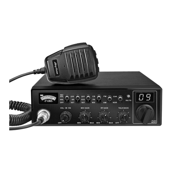
- Page 9 GETTING ACQUAINTED Front Panel No. Functions TFT LCD NB/ANL Function On / Off Switch NR Function On/Off / NR Settting Switch VOX Function On/Off / VOX Setting Switch Mode Switch: CB / PA / WX Modulation Mode Switch: FM / AM Channel 9 / Normal Switch RX(Receive) / TX(Transmit) LED Indicator Channel Display: CH and Scrolling Frequency Display...
- Page 10 Rear Panel Functions Antenna Connector Public Address Speaker Jack External Speaker Jack Power Jack Microphone DOWN Connector Microphone cable...
- Page 11 HOW TO USE YOUR RADIO Power OFF/ON 1. Turn the VOL knob clockwise to switch the radio ON, the radio may emit a beep (if the beep function is enabled). The LED display will show a channel number. 2. Turn the VOL knob anti-clockwise, until hear Ka Ta, the radio is powered off. Volume Control Turn the VOL knob clockwise to increase the Volume, Turn it anti-clockwise to decrease the Volume.
- Page 12 UP / DN Buttons On Microphone In normal operation, press UP / DN buttons on the microphone to change the channel. UP to increase, and DN to decrease the channel. In MENU mode (press the PUSH knob for about 3 seconds to activate this mode), the UP or DN buttons allows to select the mune to be set.
- Page 13 Select the CB mode Mode Select the Public Address (PA) mode Select the WX mode Select the Frequency Modulation (FM) mode Modulation Mode Select the Amplitude Modulation (AM) mode To access Instant channel 9 Instant Channel Return to the original channel selected FUNCTION MENU 1.
- Page 14 Electret (default) Microphone type setting Mic Type Dynamic Squelch (default) Scan type setting Scan Type Time ON : turn on ECHO function ECHO function setting ECHO OFF : turn off ECHO function (default) ECHO volume level 1 ~ 32 ECHO Volume Default : 28 setting 1 ~ 32...
- Page 15 5. SPECIFICATION GENERAL Modulation Mode AM/FM FM 26.565-27.405MHz(EU) Frequency Range AM/ FM 26.965-27.405MHz(EU US CA) Weather Channles 162.400-162.550MHz Frequency Tolerance ±5.0ppm Input Voltage 12/24V Dimensions 210(L)x185(W)x56(H)mm Weight 1.02kg Operating Temperature Range -10℃ to +50℃ Transmit 3A MAX Current Drain Receive Squelched 0.3A VOL Max 0.7A...
- Page 16 Warning Statement This device complies with part 15 of the FCC Rules. Operation is subject to the following two conditions: (1) This device may not cause harmful interference, and (2) this device must accept any interference including received interference that may cause undesired operation. The grantee is not responsible for any changes or modifications not expressly approved by the party responsible for compliance.
- Page 17 RF Exposure Statement This equipment complies with RF radiation exposure limits set forth for an uncontrolled environment. This equipment should be installed and operated with minimum distance 51.5cm between the radiator & your body. This radio transmitter has been approved by lndustry Canada to operate with the antenna types listed below with the maximum permissible gain and required antenna impedance for each antenna type indicated.
Need help?
Do you have a question about the 900 PRO and is the answer not in the manual?
Questions and answers