La Marzocco linea EE / AV / PADDLE, linea Series Manual
- Manual (142 pages)
Advertisement
- 1 Definition of Available Models
- 2 Installation
- 3 Machine Operation and Coffee Preparation
- 4 PID Temperature Controller
- 5 Dispensing Steam and Hot Water
- 6 Maintenance and Periodic Cleaning Operations
- 7 De-commissioning and Demolition
- 8 Mandatory Maintenance and Check-up Operations
- 9 General Warnings and Safety Specifications
- 10 Documents / Resources
Definition of Available Models
This operating manual refers exclusively to the following models, of our own manufacture:
EE Model, AV Model, PADDLE Model with 1, 2, 3 and 4 groups

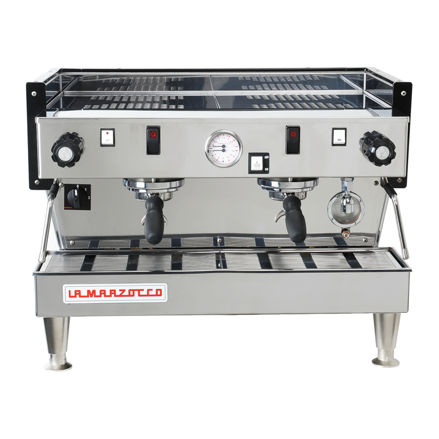
Fig. 1 - EE Model available with 1, 2, 3 and 4 groups
Legend
- Main Switch
- Water level sight glass
- Pressure gauge
- Coffee groups
- Coffee brewing control switch
- Cup warmer switch (non-UL machines)
- Hot water switch
- Manual fill switch
- Steam nozzle/wand
- Steam knob
- Hot water nozzle

Fig. 2 - Front panel of PADDLE model available with 1, 2, 3 and 4 groups
- Group lever
- Steam knob
- Pressure gauge steam boiler
- Pressure gauge coffee boiler
- Manual fill switch
General description
The models AV, EE and PADDLE are built in the 1, 2, 3 and 4 group versions and are essentially composed of the following parts:
- Water boiler (produces steam and hot water);
- Coffee ("saturation") boiler;
- Brewing groups;
- Exterior;
- Motor pump.
Description of the various parts
- Steam Boiler
The steam boiler consists of a cylindrical tank, of varying length according to the number of coffee groups, which is made of stainless steel. Each unit is subjected to a hydraulic test, at a pressure of 3 bar, and has an operating pressure of 1.5 bar. In the following, you will find a list of effective volumes and standard power ratings according to the number of groups installed:1 group 3.5 litres 1300 Watts 2 groups 7 litres 2000 Watts 3 groups 11 litres 3000 Watts 4 groups 14.5 litres 3800 Watts Higher powered heating elements are available for steam boilers in some markets. Covers are installed at either end of the cylindrical tank and on one of them there is a housing for the water heating and vapourizing electrical elements, which allow reaching operating pressure within 25' approximately. Operating pressure is maintained by a pressure switch. The water boiler has various fittings used for safety devices, for supplying hot water and steam, and for the power supply.
- Coffee Boiler
The coffee boiler is subjected to a hydraulic test, at a pressure of 16 bar, and has an operating pressure of 9 bar. In the following, you will find a list of effective volumes and power ratings according to the number of groups installed:1 group 1.8 litres 1000 Watts 2 groups 3.4 litres 1400 Watts 3 groups 5.0 litres 1600 or 1900 Watts 4 groups 3.4 + 3.4 litres 1400 +1400 Watts
(2boilers installed)It consists of a cylindrical tank, of varying length according to the number of coffee groups, which is made of stainless steel. Covers are installed at either end of the cylindrical tank and on one of them there is a housing for the water heating and vapourizing electrical elements, regulated by a precision PID Controller with a dT of ± 0.5°C which keeps the water temperature constant. This temperature can be adjusted to reach optimal temperature according to the type of coffee blend being used. The groups are welded to the boiler.
- Brewing Groups
The brew groups are made of stainless steel, in which you engage the portafilter used to hold the ground coffee; the espresso flows from the group, through a spout, into the cup(s) after the brewing button has been pressed. - Exterior
The exterior consists of painted and stainless sheet steel panels. To provide good aesthetics, to optimize ergonometrics for the operator and to reduce the chance of damage to a minimum. - Motor Pump
The rotary vane pump, is installed on the water supply tubing and is set up to operate anytime the coffee groups are activated, and through an autofill system whenever the water boiler needs to be replenished.

Fig. 3 - AV model available with 1, 2, 3 and 4 groups
Legend
- Main Switch
- Water level sight glass
- Pressure gauge
- Coffee groups
- Coffee dispensing control panel (AV model)
- Cup warmer switch (non-UL machines)
- Hot water switch
- Manual fill switch
- Steam nozzle/wand
- Steam knob
- Hot water nozzle
- Manual brew switch
General Description
The AV model machine is built in the 1, 2, 3, and 4 group versions and is essentially composed of the same parts as EE model. This model differs from EE model in that it allows the operator to choose four different quantities of water for brewing coffee. Each group, therefore, is provided with a 5 button control panel, allowing a combination of:
- a quantity of water for one normal espresso coffee;
- a quantity of water for one tall coffee;
- a quantity of water for two normal coffees;
- a quantity of water for two tall coffees.
The fifth button is used to program the other ones, as we shall see later, and as an on-off switch for continuous brewing.
Coffee brewing control panel for the AV model

Installation

Legend
 | 380/220/200 Volt cable |
 | 220/200 Volt cable |
 | Water tubing |
 | Drain tubing |
- Main Switch
- Drain piping
- Terminal
- Motor pump
- Filter outlet
- Filter inlet
- Tap
- Drain wells
- Expansion valve
- Group cover
- Bleed screw
- PID Temperature Controller
- Switch (not provided)
- Plug (not provided)
- Connectors

The machine is intended to be permanently connected to fixed wiring, and it is mandatory that a residual current device (RCD) with a rated residual operating current not exceeding 30mA is installed in accordance with AS/NZS 3000.
At each installation, the machine should be equipped with a new set of tubes for plumbing and related gaskets.
Water pressure supply must be between 0,2 and 0,6 MPa if sufficient pressure is not available we suggest that an additional water supply system is used.
Before making any electrical connections make sure that the two strain relief connectors are firmly secured to the body of the machine in order to prevent inadvertent stress on the power cables.
This machine should not be installed in kitchens.

Hazardous voltage disconnect from power supply before servicing.
The motor pump must be situated close to the machine in an accessible place for maintenance but not for accidental interference and where there is an optimal air circulation.
The manufacturer declines any responsibility for any event leading to liability suits whenever grounding has not been completed according to current local, national, and international regulations and electrical codes, or other electrical parts have been connected improperly.
This appliance is not intended for use by persons (including children) with reduced physical, sensory or mental capabilities, or with lack of experience and knowledge, unless they have been given supervision or instruction concerning the use of the appliance by a person responsible for their safety.
U.S.A. and CANDA only
Do not connect to a circuit operating at more than 150V to ground on each leg.
This machine is not suitable for outdoor use. Jets of water should not be used to clean the machine, nor should it be placed where water jets are used.
The Coffee Boiler and Steam Boiler contain water at elevated temperature. Water temperature over 125°F/52°C can cause severe burns instantly or death from scalding (Coffee Boiler 207°F/97°C - Steam Boiler 256°F/124°C)
Note:
- The drinking water mains valve and the circuit breakers for the electrical system need to be located in the most convenient position for the operator to access them easily and quickly.
- This machine complies with the standard 61000-3-11, the impedance at the supply interface must be Zmax = 0.02 Ω.
Replace fuses with the same size, type and rating F1 = 2A, 250V
In order to prevent cracks or leakage: do not store or install the Coffee machine in places where in boiler or hydraulicsystem to freeze.
Water specifications table
| Min. | Max. | ||
| T.D.S. | ppm | 90 | 150 |
| Total Hardness | ppm | 70 | 100 |
| Total Iron (Fe +2 /Fe +3 ) | ppm | 0 | 0,02 |
| Free Chlorine (Cl 2 ) | ppm | 0 | 0,05 |
| Total Chlorine (Cl 2 ) | ppm | 0 | 0,1 |
| pH | value | 6,5 | 8,5 |
| Alkalinity | ppm | 40 | 80 |
| Chloride (Cl – ) | ppm | not more | 30 |
N.B.: Test water quality (the warranty is void if water parameters are not within the range specified in the section "installation")
- Installation on the counter
The image below shows the recommended method to drill the hole on the counter.

- Water test kit
In order to enable you to check if your water supply is within the suggested ranges, La Marzocco machines will be equipped with two units of a quick water test kit (see image below) including 6 test-strips and instruction cards.
![]()
The parameters that you can measure are Total Hardness, Total Iron, Free Chlorine, Total Chlorine, pH & Total Alkalinity, Chlorides. Ideally, you should perform a test on the water BEFORE the water treatment system and again AFTER the water system in order to verify if this is actually matching our suggested ranges. Once the test has been performed, learn which treatment system is most appropriate for your particular water supply by filling out the online water calculator on our website: LA MARZOCCO WATER CALCULATOR (http://www.lamarzocco.com/water_calculator/).


MODELS "EE" "AV" and "PADDLE" 1, 2, 3 and 4 groups
- Accessories
In order to proceed with installation, it is necessary that the following are available:- Pipes carrying drinking water with a 3/8"G (BSP) end connection; (3/8" Compression for USA and Canada)
- Electrical Supply according to the specification of the espresso machine purchased (not all specifications are available in all markets):
- → Single/Three phase 220VAC - 50/60 Hz electrical connection with ground, protected receptacle and approved circuit breaker
- → Single phase 200VAC - 50/60 Hz electrical connection with ground, protected receptacle and approved circuit breaker
- → Three-phase, 380VAC - 50/60 Hz electrical connection with neutral + ground, near the bench on which the machine is installed and terminating in a suitable protected fivepole receptacle equipped with an approved circuit breaker
- Waste water drain system
- Water supply connection
In order to connect the machine up to the water mains proceed according to the indications given in the chapter about Installation and in compliance with any local/national safety standards of the location in which the machine is being installed.
The equipment is to be installed with adequate backflow protection to comply with applicable federal, state, and local codes.
To guarantee a correct and safe functioning of the machine and to maintain an adequate performance level and a high quality of the beverages being brewed it is important that the incoming water be of a hardness greater than 7°f (70ppm, 4°d) and less than 10°f (100ppm, 6°d), pH should be between 6.5 and 8.5 and the quantity of chlorides be less than 30mg/l. Respecting these values allows the machine to operate at maximum efficiency. If these parameters are not present, a specific filtration device should be installed, while always adhering to the local national standards in place regarding potable water.
Then connect the inlet of the water filter/ softener (if present) to the drinking water supply using one of the supplied stainless steel braided hoses. Before connecting the filter to the water pump, flush the water supply line and the filtration system in order to eliminate any residual particles which could otherwise get stuck in taps or valves thus preventing them from working properly. Connect the water connection of the espresso machine to the water pump outlet using one of the supplied stainless steel braided hoses. Then connect the water pump inlet to the water filter/softener outlet (if present).
Note: The water pump is a differential pressure volumetric pump and has been designed to be used exclusively with cold water. Make sure that water is always present while the pump is operating, otherwise air can be introduced into the brew boiler causing an undesireable condition and the pump can be damaged. - Electrical connections
- Power supply cord
- This is the main power supply cable that provides power to the entire espresso machine. There are different types of cable based upon the electrical requirements of the espresso machine purchased:
- → 200/220VAC 1 Phase 3-core cable with 2.5/4/6/10mm2 cross section or AWG 12/10/8 (for UL version), secured to espresso machine via a strain relief connector
- → 220VAC 3 Phase 4-core cable with 4 mm2 cross section for versions with 1, 2, 3 and 4 groups secured to espresso machine via a strain relief connector
- → 380 VAC 3 Phase 5-core cable with 2.5/6 mm2 cross section for versions with 1, 2, 3 and 4 groups secured to espresso machine via a strain relief connector.
![]()
- This is the main power supply cable that provides power to the entire espresso machine. There are different types of cable based upon the electrical requirements of the espresso machine purchased:
- Water pump motor power cord
This is the power supply for the water pump motor. The internal electronics will switch the pump motor on when needed.- 3-core cable with 1.5 mm2 cross section or 3-core AWG 16 (for UL version) secured to espresso machine via a strain relief connector.
- Quick connection between the water pump and the espresso coffee machine
The electrical connection must be made through the use of the connectors, as shown in the following figures:- View of the connectors;
![]()
- Cable connection;
![]()
- Cable tightening;
![]()
- View of the connectors;
- Power supply cord
- Waste water drain connection
The espresso machine drain is to be connected by means of the included reinforced plastic tubing. Connect one end of the reinforced plastic tubing to the drain hose connection on the left side of the espresso machine, secure with included hose clamp. Connect the other end to a suitable waste water collection system.
In case such a system is not available, and if acceptable according to local regulations, drained liquids may be collected in a suitable bucket and any necessary drain pipe extensions shall be made using steel-lined PVC tubing and suitable hose clamps.
![]()


Machine Operation and Coffee Preparation

Never remove the filter holder when water is being delivered. This operation can be extremely dangerous since the high pressure built-up inside the blind filter would spray out hot and slightly caustic water, which may cause severe burns. The Coffee Boiler contains water at elevated temperature. Water temperature over 125°F/52°C can cause severe burns instantly or death from scalding.
The machine must not be dipped in, nor splashed with, water in order to clean it. For cleaning operations, please follow the instructions listed below very carefully.
This machine is designed only for preparing coffee and hot drinks.

To improve the flavor of the espresso, the temperature of the water in the coffee boiler and therefore of the groups may eventually be raised or lowered via the digital display (please consult the Software Programming Manual for detailed instructions).
Once installation has been completed, you can proceed to hook up the filter holders (Fig. 6) called portafilters, together with their filters, to the bottom of the groups by rotating them from left to right. Before operating the various switches and thus powering up the heater elements, fill up the boiler tanks with water, as follows:
- COFFEE BOILER
The water flows inside the coffee boiler directly, as soon as the water system and purifier taps are opened. Since the in flowing water will compress the air in the boiler it will be necessary, in order to completely "saturate" the boiler-groups assembly, to remove the group cover plate (part 20 Fig. 4) and unscrew the small bolt (part 21) called bleed screws a little way so as to allow air to escape until a few drops of water leak out (see diagram below). This should be repeated for each group, then tighten the bleed screws again and reinstall the cover.
![]()
- STEAM BOILER
By turning the main switch (part 1) to position "1", the automatic fill system will be switched on which, by activating the solenoid valve and the motor pump (part 15), will fill the steam boiler up to a predetermined level selected by adjusting the probe inside the boiler itself.
N.B.
It may happen that the air inside the boiler builds up pressure (which may be detected through the pressure gauge - part 3, Fig 1, 2 or 3) To resolve this, turn the machine off and bleed the air from the groups. Once you have completed these operations, turn the main switch (part 1) to position "2" and wait for the boilers to reach operating temperature and pressure (which takes from 20 to 35 minutes, depending on the size of machine), which will be subsequently maintained at a constant value automatically.
During this time, the pointer of the lower scale on the pressure gauge (part 3, fig. 1 or 3; or part 4 fig. 2) may reach as high as 11-12 bar; this may occur any time that, while activating the groups, the motor pump forces cold water into the coffee boiler at a pressure of 8-9 bar and, simultaneously, the temperature controller regulating the temperature of the boiler itself switches on the heating elements in order to bring the water contained in such boiler up to operating temperature. However, in this case it is necessary to adjust the expansion valve (Fig. 4, part 19A) in such a way that the pressure may never exceed 12 bar.

Brewing after first installation

Once the first installation procedures are finished, before proceeding with brewing coffee, hot water and steam, please follow these steps:
- Engage the portafilters by inserting them into each group, brew water through each group for at least two minutes.
- Being careful to avoid burns, turn on each steam wand for at least one minute.
- Turn on the hot water valve for the time necessary to allow the following quantities of water to be brewed:
- At least 1 liter for a 1/2 group machine
- At least 2 liters for a 3 group machine
- At least 3 liters for a 4 group machine
For EE model - fig. 1
Take a portafilter and place some ground coffee in the filter itself: the suggested amounts (in grams) to use are laser-marked on the actual filters. Press down on the ground coffee with the supplied tamper and engage the filter holder in the group and then press the switch (part 5) thus allowing coffee to be brewed; when you have obtained your desired amount of coffee, press the switch again (part 5), at which point the machine discharges the pressure built up in the filter holder. The holder may then be removed to proceed with making another coffee, as required.
For PADDLE model - fig. 2
Take a portafilter and place some ground coffee in the filter itself: the suggested amounts (in grams) to use are lasermarked on the actual filters. Press down on the ground coffee with the supplied tamper and engage the portafilter in the group. Move the paddle handle of the group from right to left (part 1) thus allowing coffee to be brewed; when you have obtained your desired amount of coffee, return the paddle handle back to original position on the right-hand side, at which point the machine discharges the pressure built up in the portafilter. It may then be removed to proceed with making another coffee, as required. In order to pre-infuse the coffee in the filter, once the portafilter has been engaged in the group, move the paddle handle only half way from the right to left for a few seconds, then move all the way to the left in order to brew your espresso/s, until the desired dose is released in the cup, then turn off by returning the paddle handle to its original position on the right-hand side.
For AV model - fig. 3
It is essential to program the quantity of water delivered by performing the following operations with the utmost care. In case of doubt or difficulties, please contact our technical service.
Introduction

The coffee metering system is based on the amount of water which will be delivered onto the ground coffee, already set in the filter and the portafilter, which is measured through a water volume control system, which is located above the group assembly flange, where the group connects to the boiler. Inside each counter there is a paddle wheel (which we shall call wheel for simplicity) which rotates as water flows by.
The sequence of the water cycle is as follows:
group > counter
counter > solenoid valve
solenoid valve > diffuser
diffuser > coffee brewing spout
The wheel is designed in such a way as to rotate freely when water is flowing by; it sends 2 signals, every complete rotation, to the electronic module which processes them and activates the solenoid valve relay of the corresponding group, as well as the motor pump relay.
Such electronic module also processes the signal sent by the boiler's level gauge and consequently activates the relative solenoid valve relay of the same motor pump.
Procedure for programming doses
Fig. 3
Programming for the 3D/5 version
Press and hold the button with the spiral symbol for more than 4 seconds.

You can then follow the same operations as for the standard version, which are described in the following.
The LEDs stay on for 5 seconds after which, if no button has been pressed, they turn off; you must then repeat the above-mentioned procedure to turn them on again and to prepare the electronic module for programming;
- press the first button within 5 seconds and press it again once you have obtained the desired amount of coffee; at this point, the LEDs will turn off and this button will remain programmed as for the dose brewed previously;
- repeat steps for the other three buttons; any time a button has been programmed, by pressing the button with the spiral again, the LED of the programmed button(s) will remain switched off.
- once you have programmed the first 4 buttons of the first control panel from the left, the dosage programs set according to the above will be stored in memory and the 5th button (the one with the spiral) will return to its function as a continuous brewing on/off button.
N.B.
The programs for the first group from the left will become the default programs for the remaining groups, although you may wish to program these groups differently in which case you need to follow steps 1 to 5 for the remaining control panels. The leftmost control panel must be programmed first; indeed, if you were to program this last, all its settings would be automatically transferred to the other groups.
It is recommended that each group be programmed separately, from left to right. Each button also works as a switch and, therefore, you may stop coffee brewing at any time, whenever you have obtained the desired quantity, by pressing the same button.
Fault warnings
If the wheel does not send any signals to the electronic module for more than 3-4 seconds, the LED of the button which has been pressed will start flashing. This means that:
- water is not flowing over the wheel and is therefore not reaching the coffee groups, which may be due to:
- the ground coffee being too fine meaning that the coffee gets brewed too slowly (drop by drop) and therefore the wheel cannot measure the water flow within the factory-set time of the electronic module.
- insufficient water flow through the groups (i.e. onto the coffee powder) probably due to a combination of one or more of the following occurrences:
- partial blockage in one of the pipes;
- malfunctioning motor pump;
- malfunctioning solenoid valve;
- partial blockage of the diffuser screen.
- there are calcium deposits inside the water flow counter which prevent the wheel from turning properly.
- the wheel itself and the sensor (top part) of the counter, may be faulty.
Coffee brewing
Take a portafilter and place some ground coffee in the filter itself: 1 dose for the small filter, 2 doses for the larger filter. Press down on the ground coffee with the supplied tamper and engage the filter holder again into the bottom of the group and then press one of the buttons with the symbols for 1 or 2 cups, short or long.

You may press the same button again in order to terminate coffee brewing before its programmed stop. If you need an unusual amount of coffee, you may use the button with the spiral symbol and press it again once you have obtained the desired quantity.
Once the coffee has been completely brewed, the pressure in the filter holder is discharged automatically, the portafilter may then be removed to repeat the operation as needed.
GENERAL NOTIONS FOR PREPARING COFFEE
When the machine has reached its operating pressure, 1.2 - 1.5 bar which may be checked by looking at the upper scale in the pressure gauge (part 3 fig. 1, 2 or 3), and its operating temperature at the same time, with the body/group already at infusion temperature, the filter holder and filter must be heated more since they are at the lowest position of the group itself, and they are partially isolated from the same due to the rubber gasket between them. This operation may be carried out by activating the paddle (fig. 2, part 1) or the switches (part 5, fig. 1 or 3) and keeping them in the brewing position for approx. 45 seconds, at which point they must be turned off and you must wait for 2-3 more minutes. During this time, the pointer of the lower scale of the pressure gauge (part 3, fig. 1 or 3; or fig. 2, part 4) may reach as high as 11-12 bar; this may occur any time that, while activating the groups, the motor pump forces cold water into the coffee boiler at a pressure of 8-9 bar and, simultaneously, the PID controller regulating the temperature of the boiler itself switches on the heating elements in order to bring the water contained in such boiler up to operating temperature. However, in this case it is necessary to adjust the expansion valve (marked 19A in fig. 4) in such a way that the pressure may never exceed 12 bar.
The size of the coffee granules is extremely important in preparing a good cup of coffee, as is the type of coffee mix used. The ideal grind can be determined by making various coffees using the amount of ground coffee that you would normally use for each cup (we recommend at least 7 g). The best grind is that which allows coffee to flow out from the filter holder spouts neither too slowly nor too quickly.
The temperature of the water in the coffee boiler, and therefore of the groups, may eventually be raised or decreased by means of the PID temperature controller (part 22, fig.4) - see next chapter for further details. The final adjustment should be made during tuning-up, once the machine has been permanently installed. The pressure of the water on the coffee during the brewing is very important. For this reason it is important to set the by-pass on the pump at 9 bar. This value changes if there are variations on the incoming pressure from your local water system. If there are variations, make the necessary technical adjustments on the system in order to eliminate them.
PID Temperature Controller
Description
Front display description:

see also Fig. 4 - part. 20
N.B.
In 1,2,3 group machines the PID Controller is installed on left side. In 4 group machines on left and right side.
- Coffee boiler element Pilot light
Lights up while controller output 1 stays ON. i.e. heating element is ON - Display
Displays the PV (process value) or SV (setting value). When setting a parameter, its name or its value appears. - SEL key
Used to switch the PV display to/from the SV display and select a parameter block and a parameter, and register a set value. ![]() keys
keys
Used to change the SV, call parameters, and change parameter values.- Auto-tuning/self-tuning lamp
Flickers under an auto-tuning or self-tuning operation. - SV (setting value) lamp
Displays the PV (process value) in normal conditions (while the lamp is on). Press the SEL key to light up the SV lamp and display the SV. Note that the lamp stays off while parameters and data are displayed.
It flickers while the display shows the PV (process value) in standby state.

Basic operations
How to set and display the values
Press the SEL key to display the value

One press to increase the value by 1. Press and hold this key to increase to desired value then wait a few seconds to automatically exit programming function.

One press to decrease the value by 1. Press and hold this key to decrease to desired value then wait a few seconds to automatically exit programming function.

Dispensing Steam and Hot Water
STEAMING MILK
In order to allow for any condensed water in the wand to be released ALWAYS allow some steam to be discharged by turning on the valve before inserting the steam wand into the pitcher of liquid to be heated. Then insert one of the 2 nozzles (part 9, fig. 1 or 3) which are connected to the steam tap, into the liquid to be heated, turn the knob (part 10, fig. 1 or 3 gradually until steam comes out at the end of the nozzle (1).
The steam will transfer heat to the liquid raising its temperature up to boiling point. Be careful not to allow liquid to overflow in order to avoid severe burns.
To prepare milk for making cappuccino with the right amount of foam, go through the following steps:
- Place the container half-full of milk under the steam nozzle
- Open the tap immediately and bring the temperature of the milk to your desired temperature
- You can then pour this milk into a cup containing warm espresso and you will end up with a fresh cappuccino
In order to prevent part of the liquid to be heated from being sucked back into the boiler (due to a possible temporary decompression inside the boiler tank) which would cause both the steam and the liquid delivered by nozzle part 9 and nozzle part 11 respectively to have a bad odour, we recommend that you de-vapourize the machine once or twice for just a few seconds, which consists of quickly opening and closing the tap (part 10) with the nozzle (part 9) not immersed in the liquid before starting to steam it. Be careful not to burn yourself with the steam. Furthermore, once you have immersed the steam wand into the liquid to be steamed in the pitcher, open the steam tap immediately. Once the liquid has been heated, follow this procedure:
- lower the steam pressure
- remove the pitcher
- close the steam tap
DISPENSING HOT WATER
You can obtain hot water by using the fixed nozzle (fig. 1 or 3), located between the group furthest to the right and the steam nozzle (part 9, fig. 1 or 3), and by pressing the button (part 7, fig. 1 or 3) which commands hot water delivery.

Maintenance and Periodic Cleaning Operations
If the above-mentioned instructions are not adhered to the manufacturer cannot be held responsible for damage to persons or things.
In order to prevent cracks or leakage: do not store or install the coffee machine in places where temperature may cause water in boiler or hydraulic system to freeze.
The machine is intended to be permanently connected to fixed wiring, and it is advisable that a residual current device (RCD) with a rated residual operating current not exceeding 30mA is installed.
The machine must be installed so that qualified technical personnel can easily access it for eventual maintenance.
The machine must not be dipped in, nor splashed with, water in order to clean it. For cleaning operations, please follow the instructions listed below very carefully.
Do not remove the filter holder while relative group is brewing hot liquids. The Coffee Boiler contains water at elevated temperature. Water temperature over 125°F / 52°C can cause severe burns instantly or death from scalding.
This machine is for professional use only and should be installed in locations where its use and maintenance is restriced to trained personnel.
Jets of water should not be used to clean the machine, nor should it be placed where water jets are used.
Cleaning groups and drain wells
Insert the blind filter into portafilter and put the correct amount of espresso cleaning product (following the product's instructions) into the filter, engage the portafilter into the group you want to clean.
- Press the brewing button for said group, as if you were making a regular cup of coffee. Stop the water after about 15-20 seconds.
- Start and stop the group several times until you notice clear water being released instead of soapy water when you remove the portafilter.
Do not remove the portafilter when group is actually brewing water. - Rinse the group using a normal filter in the portafilter, by running hot water through it several times.
Cleaning filters and filter holders
With daily cleaning of the stainless steel filters and portafilters it is sufficient to clean them with water and a cloth or appropriate brush. Otherwise, using an espresso cleaning product, following the product's instructions put the correct dose in about 1/2 a litre of water inside a heatresistant container and heat.
- If using stainless steel portafilters with snap-on spouts remove the spout. Immerge filters and metallic parts of portafilters (not handles) in the hot solution and leave them submerged for about 30 minutes.
- Rinse thoroughly with clean water and run hot water through the group several times with the filter and portafilter engaged.
- Make one cup of coffee in order to remove any unpleasant flavour.
Cleaning the drain collector
Remove the drain tray grill every night, pull out the water drain collector and clean it thoroughly. Also inspect and clean the drain well (part 19) at least twice a week, and remove any leftover grounds with a tablespoon.
Cleaning the body
Wipe the stainless steel surfaces with a soft cloth in the direction of the glazing marks, if any. Do not use any alcohol or solvents whatsoever on painted or imprinted parts in order not to damage them.
Cleaning the hot water and steam nozzles
Steam nozzles must be cleaned immediately after use with a damp cloth and by producing a short burst of steam (being careful to avoid burns) so as to prevent the formation of deposits inside the nozzles themselves, which may alter the flavour of other drinks to be heated.

Cleaning the diffuser screens (infusion filter)
Due to filter holder discharge operations (subsequent to coffee brewing), a certain amount of coffee grounds may slowly build-up on and obstruct, even partially, the infusion filter. To clean, you must first remove it by unscrewing the retainer screw, then soak in espresso detergent powder.

Motor Pump
The motor pump is of the positive-displacement type and can develop a pressure of 14 bar. The operating pressure is 8-9 bar and is factory preset during testing; however, such pressure may vary from place to place since the pump pressure is affected by the incoming water mains pressure. You must always check the pressure itself by looking at the lower scale on the pressure gauge (part 3, fig. 1 or 3; part 4, fig. 2) whenever you are brewing coffee, and you can increase such pressure, as required, by turning the by-pass screw (below the plug located on the side to which the pump power supply is connected) clockwise, or reduce it by turning the screw counterclockwise. Adjust pressure only when at least one group is brewing coffee.
When you activate the motor pump by pressing the specific button (part 8, fig. 1 or 3) you also give pressure directly to the coffee boiler. If you activate the motor pump when the machine is cold, a startup pressure of 8-9 bar will develop; thus, once the heating elements start working and the water temperature increases, the liquid will expand increasing the start-up pressure by about 3 bar, for a total pressure of 11 bar. Once operating pressure is reached, the expansion (safety) valve (part 19A) should start working by discharging a few drops of water, in order to prevent such pressure from exceeding 12 bar. If the pressure exceeds 12 bar, you must adjust the valve by unscrewing the cap slightly. If this is not sufficient, remove the valve and clear away any calcium deposits. This remedy is valid also if the valve remains open in the drain position (i.e. the pressure cannot increase to 8 bar approx.).
If the machine has not been used for more than 8 hours or, in any case, after long periods of being idle, in order to use the machine to its full potential it is necessary to perform some cleaning cycles before brewing beverages as follows:
- Groups: with the portafilters engaged in the groups brew water through each for at least two minutes
- Being careful to avoid burns, turn on each steam wand for at least one minute.
- Turn on the hot water valve for the time necessary to allow the following quantities of water to be brewed:
At least 1 liter for a 1/2 group machine
At least 2 liters for a 3 group machine
At least 3 liters for a 4 group machine
If the machine is not going to be used for long periods of time, it is advisable to follow these safety indications:
- Disconnect the machine from the water mains or interrupt the water connection via a mains tap.
- Disconnect the machine from the electrical mains.
- Steam boiler draining: Yearly, we recommend to fully drain the steam boiler by means of the specific drain cock located on the side of the boiler or under the boiler
- Depressurize the steam boiler
Press and hold the encoder knob to set the espresso machine to "OFF", then push down the steam lever in order to depressurize the steam boiler.
De-commissioning and Demolition
Start by setting the main switch (part 1) to the "0" position.
Disconnecting from the power outlet
In case the machine is connected through the plug (part 24), make sure that the switch (part 23) is also in the Off position before disconnecting. Disconnect the motor pump (part 15) by pulling out its special plug (part 25).
Disconnecting from the water system
Shut off the water supply by closing the specific tap located upstream of the purifier inlet. Disconnect the water pipe at the purifier (part 17) inlet, which is located just downstream of the special tap (part 18), which has been closed in advance.
Proceed to remove the drain well piping (part 19).
At this point, the machine may be removed from the bar, being very careful not to drop it.
The machine is made out of various materials and therefore, if you do not intend to put it back in service, it must be taken to a special disposal company which will select the materials which can be recycled and discard the others.
Current regulations make it illegal to discard such machine by leaving it on public grounds or on any private property.
Mandatory Maintenance and Check-up Operations
These operations are in addition to the Maintenance and Periodic Cleaning Operations.
The following maintenance and check-up operations sould be carried out by a qualified technician.
N.B. These periodic maintenance operations are not covered by warranty.
EVERY THREE/FOUR MONTHS
- Replace group gaskets
- Replace diffuser screens
- Clean auto-fill probe
- Check vacuum breaker for proper operation
- Inspect water inlet valve
- Inspect drain system for leaks or clogs
- Check flow rate for each group
- Check brew temperature
- Check that brew pressure is at 9bar
- Check all switches for proper operation
- Check/note water hardness
(Water quality must be within the range of parameters specified in the chapter on Installation, otherwise warranty is voided)
If AV Model:
- Check shot volumes
- Test flowmeter's ohm value (ohm value is acceptable if greater than 1.8 K ohm, and less than 2.2 K ohm
If MP Model:
- Rebuild MP valve
EVERY SIX MONTHS (in addition to the above)
- Rebuild steam assemblies
EVERY YEAR (in addition to the above)
- Replace portafilter baskets
- Inspect group valve plungers
- Inspect vacuum breaker
- Inspect steam boiler pressurestat
- Inspect contactor
- Replace over-pressure valve
- Accurate control of the tightness at 2,4Nm of each cable on the terminal block.
EVERY 3 YEARS (in addition to the above)
- Check the condition of the inside of boilers and if necessary rinse out with a proper cleaning product allowed for food and beverage appliances.
General Warnings and Safety Specifications
This machine is for professional use only and should be installed in locations where its use and maintenance is restriced to trained personnel. Children are forbidden to operate or play with the machine.
The Coffee machine must be placed in a horizontal position on a counter higher than 80 cm from the ground.
This machine is not suitable for outdoor use. Jets of water should not be used to clean the machine, nor should it be placed where water jets are used.
As already mentioned in the preceding notes, the manufacturer shall not be held responsible for damage to objects, animals and/or people whenever the machine has not been installed according to the instructions contained in this manual, and is not used to do what it was designed for (i.e. preparing coffee and hot drinks).
- Important safeguards
- The weighted sound pressure level of the machine is lower than 70dBA.
- Use, cleaning and maintenance of this coffee machine are realized by people (including children more than 8 years of age) with reduced physical, sensory or mental capabilities, or lack of experience and knowledge, as long as they have been given supervision or instructions concerning the use of the appliance by a person responsible for their safety and if they understand dangers.
- Children should be supervised to ensure that they do not play with the appliance.
- Keep the appliance and its cord out of the reach of children less than 8 years of age.
- This operating manual is an integral and essential part of the product and must be supplied to users. Users are asked to read the enclosed warnings and cautions carefully, as they provide valuable information concerning safety during installation, operation and maintenance. This manual must be kept in a safe place and be available for consultation to new and experienced users alike.
- Ensure product's integrity by inspecting the packaging, making sure it presents no signs of damage which might have affected the enclosed machine.
- Check the machine's integrity after having carefully removed the packaging.
Note: In case of doubt, do not go on any further and contact your dealer or retailer immediately. They will send out specialized personnel authorized to perform service on the espresso machine. - Packaging (boxes, plastic bags, foam parts and whatever else) must not be left around within easy reach of children, due to the potential danger it represents, nor be discarded in the environment.
- Check to see that data on the rating plate corresponds to those of the main electrical supply which the machine will be hooked up to.
- The equipment must be installed to comply with the applicable federal, state or local electrical and plumbing codes. The installation also must comply to the manufacturer's instructions, and must be performed by qualified and authorized personnel.
- Incorrect installation may cause for injury/damages to people, animals or objects, for which the manufacturer shall not be held responsible.
- Safe electrical operation of this device will be achieved only when the connection to the power outlet has been completed correctly and in observance of all local, national, and international electrical codes and safety regulations, and particularly by grounding the unit. Make sure grounding has been done properly as it represents a fundamental safety requirement. Ensure qualified personnel check such connection.
- Furthermore, you must ensure that the capacity of the available electrical system is suitable for the maximum power consumption indicated on the espresso machine.
- We do not recommend using adapters, multiple plugs and/or extension cords. If you cannot avoid using them, make sure that they are exclusively of the kind which conforms to local, national, and international electrical codes and safety regulations, being careful not to exceed the power and current ratings indicated on such adapters and extension cords.
- This device must be used exclusively for the functions it has been designed and built for. Any other application is inappropriate and dangerous. The manufacturer shall not be held responsible for any damages caused by improper and/or irrational use. This machine should not be installed in kitchens.
- Using any electrical device requires that certain fundamental rules be observed. In particular:
- do not touch the device with wet or humid hands and feet;
- do not use the device while having no shoes on your feet;
- do not use extension cords in bath or shower rooms;
- do not unplug the device from the power outlet by pulling on the power supply cable;
- do not expose the device to atmospheric agents (rain, sun, etc.);
- do not allow children or untrained people to use this device;
- do not clean the control panel with a wet cloth since it is not watertight.
- Before carrying out any maintenance and/or cleaning operations, turn the main switch, which is located on the front left of the machine, to the "0" or "OFF" position, and disconnect the machine from the electrical network by unplugging the cord or by switching off the relative circuit breaker. For any cleaning operation, follow exclusively the instructions contained in this manual.
- In case the machine is operating in a faulty manner or breaks down, disconnect it from the electrical network (as described in the preceding point) and close the water supply valve. Do not attempt to repair it. Contact a qualified and authorized professional to perform any repair. Any repairs must be performed exclusively by the manufacturer or by an authorized centre using only original parts. Non compliance with the above could compromise the safe operation of the machine.
- You should plan to make use of an omnipolar connector during installation, as required by local, national, and international electrical codes and regulations.
- In order to avoid dangerous overheating problems, it is recommended that the power supply cable be fully unfurled.
- Do not obstruct air intake and exhaust grilles and, in particular, do not cover the cup warmer tray with cloths or other items.
- The machine's power supply cable must not be replaced by users. In case the power supply cable becomes damaged, shut off the machine and disconnect the machine from the electctrical network by switching off the relative circuit breaker and close off the water supply; to replace the power supply cord, contact qualified professionals exclusively.
- These instructions are also available in an alternative format on a website http://techcenter.lamarzocco.com.
- The machine should be placed on a flat counter and must be placed in settings with the following temperatures:
Minimum room temperature: 5°C/41°F;
Maximum room temperature: 32°C/89°F. - Check the package to make sure that the following accessories are included:
- a number of 1-dose and 2-dose portafilters according to the number of groups;
- replacement 1-dose and 2-dose filter baskets
- 1 tamper
- 1 blind filter
- cleaning detergent, for the groups
- 3 stainless steel braided hoses for water connections
- 1,5 mt of reinforced plastic tubing for drainage
- 1 hose clamp
- If the machine has been temporarily housed in settings with a room temperature of less 0°C/32°F, the machine must be placed in a warmer environment in order to gradually defrost the hydraulic system prior to use.
- Water pressure supply must be between 0,2 and 0,6 MPa. The maximum inlet water pressure shall be at least 1,0 MPa (Denmark, Norway, Sweden).
COMMON DIMENSIONS AND WEIGHTS FOR THE LINEA SERIES

| LINEA | 1 group | 2 groups | 3 groups | 4 groups |
| A cm/inch | 45.5/18 | 45.5/18 | 45.5/18 | 45.5/18 |
| B cm/inch | 56/22 | 56/22 | 56/22 | 56/22 |
| C cm/inch | 49/20 | 69/28 | 93/37 | 117/46 |
| WEIGHT [kg/lb] | 41/90 | 59/130 | 73/164 | 107/236 |
La Marzocco S.r.l.
Via La Torre 14/H
Località La Torre
50038 Scarperia e San Piero
(Firenze) - ITALIA
www.lamarzocco.com
info@lamarzocco.com
T: +39 055 849 191
F: +39 055 849 1990
Documents / Resources
References

Download manual
Here you can download full pdf version of manual, it may contain additional safety instructions, warranty information, FCC rules, etc.
Download La Marzocco linea EE / AV / PADDLE, linea Series Manual
Advertisement


Need help?
Do you have a question about the linea Series and is the answer not in the manual?
Questions and answers