TSC PRINTRONIX AUTO ID TE200 Series, PRINTRONIX AUTO TE300 / TE210 / TE310 Manual
- Service manual (48 pages)
Advertisement
- 1 Fundamental of the System
- 2 Electronics
-
3
Mechanism
- 3.1 Replacing the Planten Roller
- 3.2 Replacing the Main Board
- 3.3 Replacing the Stepping Motor
- 3.4 Replacing the Gap Sensor Module
- 3.5 Replacing Black Mark Sensor Module
- 3.6 Replacing Platen Roller Assembly
- 3.7 Replacing Stepping Motor
- 3.8 Installing the Cutter Module (TE210/TE310 Series Option)
- 3.9 Installing the Peeler Module (TE210/TE310 Series Option)
- 3.10 Replacing the Key Module (LCE MODULE / Option)
- 3.11 Replacing the Print Head Open Sensor Assembly
- 3.12 Replacing the Encoder Assembly
- 3.13 Replacing the Label Guide Module
- 3.14 Replacing Wi-Fi module Assembly (TE210/TE310 Series option)
-
4
TroubleShooting
- 4.1 Power indicator does not illuminate
- 4.2 Not Printing
- 4.3 Memory full ( FLASH / DRAM )
- 4.4 Poor Print Quality
- 4.5 Skip labels when printing
- 4.6 The printing position of small label is incorrect
- 4.7 Missing printing on the left or right side of label
- 4.8 Wrinkle problem
- 4.9 Gray line on the blank label
- 4.10 Irregular printing
- 5 Maintenance
- 6 Documents / Resources
Fundamental of the System
Printer Overview
Front View

- Paper exit chute
- LED indicator
- Feed/Pause button
- Top cover open tab
Interior View

- Printer top cover
- Ribbon supply spindle
- Ribbon supply hub
- Ribbon rewind hub
- Ribbon rewind spindle
- Fixing tabs
- Media supply spindle
- Print head release button
- Print head
- Media guide adjustment knob
- Media guide
- Platen roller
- Gap sensor
- Black mark sensor
Rear View

- Power switch
- Power jack socket
- USB interface (USB 2.0/Hi-Speed mode)
- USB host (TE210/TE310 Series only)
- RS-232 interface (TE210/TE310 Series only)
- Ethernet interface (TE210/TE310 Series only)
Electronics
Summary of the Board Connectors
Main board top


Main board bottom


TE210/310 SERIES ONLY:
RS-232C
| PIN | CONFIGURATION |
| 1 | +5 V |
| 2 | TXD |
| 3 | RXD |
| 4 | CTS |
| 5 | GND |
| 6 | RTS |
| 7 | N/C |
| 8 | RTS |
| 9 | N/C |
USB Device
 | PIN | CONFIGURATION |
| 1 | N/C | |
| 2 | D- | |
| 3 | D+ | |
| 4 | GND | |
 | PIN | CONFIGURATION |
| 1 | 5V | |
| 2 | D- | |
| 3 | D+ | |
| 4 | GND |
Ethernet
| PIN | CONFIGURATION |
| 1 | Tx+ |
| 2 | Tx- |
| 3 | Rx+ |
| 4 | N/C |
| 5 | N/C |
| 6 | Rx- |
| 7 | N/C |
| 8 | N/C |
Mechanism
Please turn off the power and unplug the power adapter before replacing parts.
Replacing the Planten Roller
- Open the printer cover. Use a tool to take the platen roller off. Replace the platen roller.
![]()
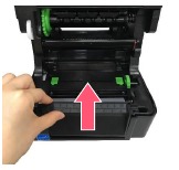
- Remove the 4 screws on media holder and disengage it.
- Remove the 2 screws on the print engine which besides the platen roller.

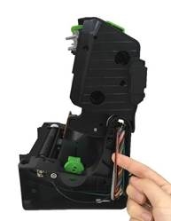
- Please remove the screw and all of the cables connected to the main board and disengage the print engine.
![]()
- Push the print engine forward and leave the slots, then lift it up to disconnect the print cover assembly.


- Reassemble the parts in the reverse procedure.
![]()
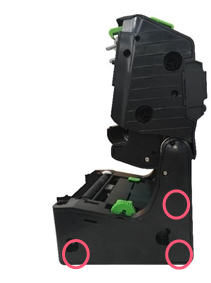
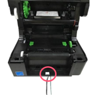
Print engine mechanism measurements

Bottom View
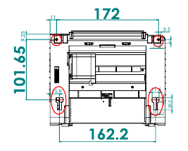
Note:
- All dimensions in millimeters.
- There are 4 location holes in this print engine mechanism, the fixing location holes are marked in red on bottom view drawing which can be fixed by the customer's reference.
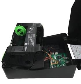
Replacing the Main Board
- Remove the printer engine
![]()
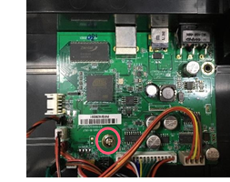
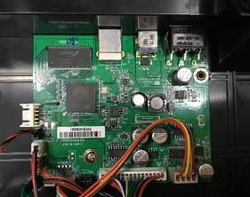
- Remove/replace the main board.
![]()
- Reassemble the parts in the reverse procedure.
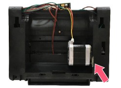
Replacing the Stepping Motor
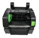
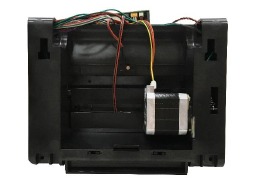
- Remove the print engine mechanism.
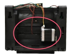
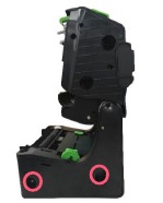
- Turn the print engine mechanism upside down and the stepping motor is installed below as indicated.
![]()
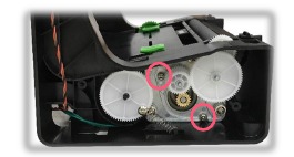
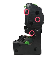
- Remove the 3 screws on the left side lower cover and open it.


- After the stepping motor left side lower cover opened, please remove the two screws as indicated to disengage the stepping motor module.
![]()
- Reassemble the parts in the reverse procedures.
![]()
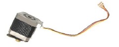
- Disconnect the stepping motor connectors on the main board.
![]()
- Remove/replace the stepping motor module.
- Reassemble the parts in the reverse procedure.
Replacing the Gap Sensor Module
- Remove the print engine.
- Turn the print engine upside down and remove the screw as indicated.

- Remove/replace the gap sensor (receiver).

- Remove the 3 screws on lower print engine right side cover as indicated and open it.
![]()
- Remove/replace the gap sensor emitter.
![]()
- Reassemble the parts in the reverse procedure.


Replacing Black Mark Sensor Module
- Remove the stepping motor module.
- Open the Mylar film cover.
![]()
- Remove the screw on the black-mark sensor module. Remove/replace the black-mark sensor module.

- Reassemble the parts in the reverse procedure.

Replacing Platen Roller Assembly
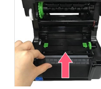
- Open the printer top cover then push the print head release button to open the print head mechanism.
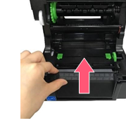
- Remove the lower front panel.
![]()
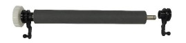
- Disengage the platen roller by pulling out the tabs located on each side. Rotate the tabs into the upward position. (see pictures below)


- Pulling upward to remove/replace the platen roller assembly.
![]()
- Reassemble the parts in the reverse procedure.
Replacing Stepping Motor
- Open the printer top cover and press the print head release button to open the print head mechanism.
- Disengage the print head module by push it forward and leave the slots as indicated.

- Disconnect the ground line (green cable) and print head harness.
- Push down and release the print head bracket hooks as indicated.

- Push the front tab of the print head bracket to the right side and open the print head bracket as pictured.


- Remove/Replace the print head assembly.

- Reassemble the parts in the reverse procedures.

Installing the Cutter Module (TE210/TE310 Series Option)
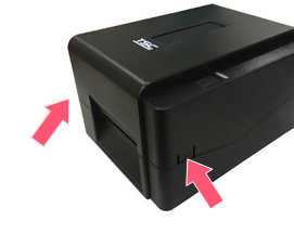
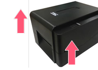
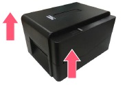
- Open the printer top cover by pressing the top cover open tabs located on each side of the printer.
![]()
- Push the print head release button to open the print head mechanism.
- Remove the lower front panel.
![]()
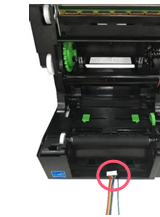
- Insert the cable and ground line of cutter module through the hole as indicated to the main board.
- Remove the four screws on media holder and disengage it.
![]()
- Connect the cable and ground line to the socket on main board as indicated.

- Push down the cutter module and fix on the lower front panel location hole.

- Complete the installation of cutter module.
- Reassemble the parts in the reverse procedures.


Installing the Peeler Module (TE210/TE310 Series Option)
- Open the printer top cover by pressing the top cover open tabs located on each side of the printer.
![]()
- Push the print head release button to open the print head mechanism and remove the lower front panel.
![]()
- Insert the cable and ground line of peeler module through the hole as indicated to the main board.
- Remove the four screws on media holder and disengage it.
![]()
- Connect the cable and ground line to the socket on main board as indicated.

- Push down the cutter module and fix on the lower front panel location hole.

- Complete the installation of cutter module.
- Reassemble the parts in the reverse procedures.


Replacing the Key Module (LCE MODULE / Option)
- Take out the print engine mechanism.
- Remove the three screws on right side upper cover and open it.
![]()
- After the right side upper cover opened, please disengage the LED module.
- Remove the two screws and cable on the LED key module.

- Remove/replace the LED key module
- Reassemble the parts in the reverse procedures.

Replacing the Print Head Open Sensor Assembly
- Remove the print engine.
- Disconnect the three screws to remove the right side lower cover.
![]()
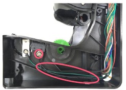
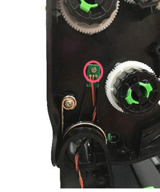
- Remove the print head open sensor by disengage the screw and cable (black) as indicated.
![]()
- Reassemble the parts in the reverse procedure.
Replacing the Encoder Assembly
- Uninstall the print engine mechanism.

- Open the print engine mechanism, and then turn to left side to disconnect six screws as indicated to remove upper and lower cover.

- Remove the screw on the Encoder assembly.
![]()
- Push the latch on ribbon base hinge to left side, pull out the ribbon base hinge and remove the Encoder assembly.


- Reassemble the parts in the reverse procedure.
Replacing the Label Guide Module
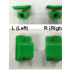
- Please check the direction of label guide (L: Left; R: Right).
![]()
- Check label guide shaft direction. The bottom side has round marks as indicated.

- Place the label guide shaft as below. The round mark is at the bottom side. Please notice about the placement position 1, 2, and 3 at right side and left side.


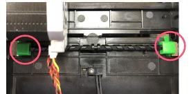
- Push the label guide R and L to the shaft.


- Push the label guide R and L to the shaft and touch the cover.
![]()
- Push the label guide R and L upward.

- Push the label guides to the end of center.

Check if the shaft is fit to the fix hole of the mechanism.


- Install the knob to the shaft.

- Reassemble the parts in the reverse procedures.

Replacing Wi-Fi module Assembly (TE210/TE310 Series option)
- Remove the print engine.
- Remove the three screws on lower print engine right side cover as indicated and open it.
Remove the three screws on Wi-Fi module assembly and disconnect the connectors. Remove/Replace the Wi-Fi module assembly. Reassemble the parts in the reverse procedure.


Note:
The Wi-Fi module and bluetooth module are not coexistence.
When install the Wi-Fi module assembly, please follow the cable loading path as shown.

TroubleShooting
| Problem | Possible Cause | Recovery Procedure |
Power indicator does not illuminate |
|
|
|
|
|
|
|
|
|
|
|
|
|
|
Not Printing |
|
|
Memory full ( FLASH / DRAM ) |
|
|
Poor Print Quality |
|
|
Skip labels when printing |
|
|
The printing position of small label is incorrect |
|
|
Missing printing on the left or right side of label |
|
|
Wrinkle problem |
|
|
Gray line on the blank label |
|
|
Irregular printing |
|
|

Maintenance
This session presents the clean tools and methods to maintain the printer.
- For Cleaning
Depending on the media used, the printer may accumulate residues (media dust, adhesives, etc.) as a by-product of normal printing. To maintain the best printing quality, you should remove these residues by cleaning the printer periodically. Regularly clean the print head and supply sensors once change a new media to keep the printer at the optimized performance and extend printer life. - For Disinfecting
Sanitize your printer to protect yourself and others and can help prevent the spread of viruses. ![]()
- Set the printer power switch to O (Off) prior to performing any cleaning or disinfecting tasks. Leave the power cord connected to keep the printer grounded and to reduce the risk of electrostatic damage.
- Do not wear rings or other metallic objects while cleaning any interior area of the printer.
- Use only the cleaning agents recommended in this document. Use of other agents may damage the printer and void its warranty.
- Do not spray or drip liquid cleaning solutions directly into the printer. Apply the solution on a clean lint-free cloth and then apply the dampened cloth to the printer.
- Do not use canned air in the interior of the printer as it can blow dust and debris onto sensors and other critical components.
- Only use a vacuum cleaner with a nozzle and hose that are conductive and grounded to drain off static build up.
- All reference in these procedures for use of isopropyl alcohol requires that a 99% or greater isopropyl alcohol content be used to reduce the risk of moisture corrosion to the printhead.
- Do not touch printhead by hand. If you touch it careless, please use 99% Isopropyl alcohol to clean it.
- Always taking personal precaution when using any cleaning agent.

Cleaning Tools
- Cotton swab
- Lint-free cloth
- Brush with soft non-metallic bristles
- Vacuum cleaner
- 75% Ethanol (for disinfecting)
- 99% Isopropyl alcohol (for printhead and platen roller cleaning)
- Genuine printhead cleaning pen
- Mild detergent (without chlorine)
Cleaning Process:
| Printer Part | Method | Interval |
| Print Head |
| Clean the print head when changing a new label roll. |
| Platen Roller |
| Clean the platen roller when changing a new label roll |
| Peel Bar | Use the lint-free cloth with 99% Isopropyl Alcohol to wipe it. | As needed |
| Sensor | Use brush with soft non-metallic bristles or a vacuum cleaner, to remove paper dust. Clean upper and lower media sensors to ensure reliable Top of Form and Paper Out sensing. | Monthly |
| Exterior | Clean the exterior surfaces with a clean, lint-free cloth (water-dampened cloth). If necessary, use a mild detergent or desktop cleaning solution then use the 75% Ethanol to wipe it. | As needed |
| Interior | Clean the interior of the printer by removing any dirt and lint with a vacuum cleaner, as described above, or use a brush with soft non-metallic bristles then use the 75% Ethanol to wipe it. | As needed |
Documents / ResourcesDownload manual
Here you can download full pdf version of manual, it may contain additional safety instructions, warranty information, FCC rules, etc.
Download TSC PRINTRONIX AUTO ID TE200 Series, PRINTRONIX AUTO TE300 / TE210 / TE310 Manual
Advertisement


Need help?
Do you have a question about the PRINTRONIX AUTO ID TE200 Series and is the answer not in the manual?
Questions and answers