TSC PRINTRONIX TDP-247 Series User Manual
Desktop barcode printers
Hide thumbs
Also See for PRINTRONIX TDP-247 Series:
- Programming manual (434 pages) ,
- Service manual (60 pages) ,
- User manual (47 pages)

Related Manuals for TSC PRINTRONIX TDP-247 Series


Summary of Contents for TSC PRINTRONIX TDP-247 Series
- Page 1 ;’RFTGTT5RT12 TDP-247 Series Direct Thermal Desktop Barcode Printers Series Lists: User Manual TDP-244 / TDP-245 TDP-245 Plus / TDP-247 / TDP-345 Series...
- Page 2 All other trademarks are the property of their respective owners. Information in this document is subject to change without notice and does not represent a commitment on the part of TSC Auto ID Technology Co. No part of this manual may be reproduced or transmitted in any form or by any means, for any purpose other than the purchaser’s personal use, without the...
-
Page 3: Table Of Contents
Table of Contents 1. Introduction ........................................1 2. Operation Overview ......................................2 2.1 Unpacking and Inspection ....................................2 2.2 Equipment Checklist ....................................2 2.3 Printer Overview ......................................4 2.3.1 Front View ......................................4 2.3.2 Rear View ......................................5 3. Setup ..........................................6 3.1 Setting up the Printer ....................................6 3.2 Loading the Label Stock....................................7 3.3 External Label Roll Mount Installation (Option) ............................8 3.4 Peel-Off Installation Assembly (Option) ................................9... - Page 4 4.2 Regular Button Function .................................... 16 4.3 Power-on Utilities ....................................... 17 5. TSC Console ........................................18 5.1 Start TSC Console ..................................... 18 5.2 Printer Function ......................................20 5.3 Setting Post-Print Action .................................... 21 6. TroubleShooting ......................................22 7. Maintenance ........................................22 8.
-
Page 5: Introduction
This document provides an easy reference for operating this printer. TSC printers include the Windows labeling software for creating your label template. For system integration, the TSPL/TSPL2 printer programming manual or SDKs can be found on TSC website at: https://www.tscprinters.com. -
Page 6: Operation Overview
2. Operation Overview 2.1 Unpacking and Inspection This printer has been specially packaged to withstand damage during shipping. Please carefully inspect the packaging and printer upon receiving the bar code printer. Please retain the packaging materials in case you need to reship the printer. 2.2 Equipment Checklist ... - Page 7 Dealer option Peel off module assembly Regular cutter (Guillotine cutter) Full cut: Media thickness: 0.06~ 0.19mm (Media type: receipt and label liner w/o glue) Partial cut: Media thickness: 0.06~0.12mm (Media type: receipt and label liner w/o glue) Note: Except for the linerless cutter, all regular/heavy duty/care label cutters DO NOT cut on media with glue. ...
-
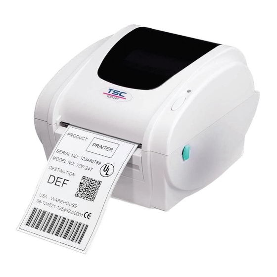
Page 8: Printer Overview
2.3 Printer Overview 2.3.1 Front View Label Opening Top Cover Clear Window LED Indicator Feed Button Top Cover Open Lever Backing Paper Opening Front cover... -
Page 9: Rear View
2.3.2 Rear View Rear Paper Guide USB Interface Centronics Interface RS-232C DB-9 Interface Power Jack Power Switch Note: The interface picture here is for reference only. Please refer to the product specification for the interfaces availability. -
Page 10: Setup
3. Setup 3.1 Setting up the Printer Place the printer on flat surface. Make sure the printer is power off. Connect the printer to the computer with the provided USB cable. Plug in the power cord. Note: Please switch OFF the printer before plugging in the power cord to printer power jack. -
Page 11: Loading The Label Stock
3.2 Loading the Label Stock Insert a 1” label spindle into a paper roll ( * f your paper core is 1 inch, remove the 1.5” core adapter from the fixed tab. If label width is 4 inch wide, two fixing tabs are not required.) Paper Roll 1.5”... -
Page 12: External Label Roll Mount Installation (Option)
3.3 External Label Roll Mount Installation (Option) Attach an external label roll mount on the bottom of the printer. Install a roll of label on the external label roll mount. Feed the label to the external label feed opening through the rear label guide. Open the printer top cover and thread the label. -
Page 13: Peel-Off Installation Assembly (Option)
3.4 Peel-Off Installation Assembly (Option) Open the top cover. Unscrew the 6 screws in the lower inner cover. Upside down the printer. Unscrew the 2 screws at the lower inner cover. Remove the screw at memory card cover. - Page 14 Hold the lower cover and lift up the top cover opening levers to separate the lower inner cover from the lower cover. Thread the harness red connector through the cable hole at the front side of lower inner cover. Plug the red peel off module harness connector at the Install one side first location JP17 (TDP-245) / JP19 (TDP-245...
-
Page 15: Loading Label In Peel-Off Mode (Option)
3.5 Loading Label in Peel-Off Mode (Option) Open the peel-off module by pulling it out. Thread the label, printing side facing up, through the label guides and place it on top of the platen. Thread the label through the liner opening, which is beneath the roller. -
Page 16: Cutter Module Installation (Option)
3.6 Cutter Module Installation (Option) Pull the top cover open levers to open the top cover. Remove the front panel from the lower cover. Remove 6 screws on the lower inner cover. Upside down the printer. Remove two screws at the hinge Remove the screw that fixes the memory card cover. - Page 17 TDP-245 Model TDP-245 Plus/TDP-247/TDP-345 Model Plug in the Cutter Driver IC at U14(TDP-245) / U30(TDP-245 Plus/TDP-247/TDP-345) socket on the main board. Hold the lower cover and lift up the lower inner cover. Arrange the cutter module harness through the bezel. Connect the cutter module harness to the 4-pin socket on printer PCB.
-
Page 18: Loading Label In Cutter Mode (Option)
3.7 Loading Label in Cutter Mode (Option) Open the printer top cover. Insert the label spindle into label roller. Place a label roll to label roll mount. Thread the paper, printing side face up, through the label guide, platen and cutter module paper outlet. Adjust the black center-biased label guides to fit edge of the label backing. -
Page 19: Install Memory Card
3.8 Install Memory Card Upside down the printer. Remove 1 screw and open the memory card cover. TDP-245Plus TDP-245 Model TDP-247/TDP-345 Model (Option) (SD card) Plug the memory card on main board. Install the card cover back to the printer. -
Page 20: Led And Button Functions
4. LED and Button Functions 4.1 LED Indicator Color Meaning Solid: Power is on and ready to be used. (Green) Flash :System is downloading data or printer is paused. System is clearing data. (Amber) Solid - Printer head open, cutter error. (Red) Flash - Printing error, such as paper empty, paper jam, ribbon empty, or memory error etc. -
Page 21: Power-On Utilities
4.3 Power-on Utilities Power-on Utilities provides the basic functions and can be activated by below procedures: Turn off the power > Hold the Feed button > Open the power > Release the button depending on the the color of the LED. Sequences of the settings: LED Colors Green... -
Page 22: Tsc Console
5. TSC Console TSC Console is a management tool combining the Printer Management, Diagnostic Tool, CommTool and Printer Webpage settings, which enables you to adjust printer’s settings/status; change printers’ settings; download graphics, deploy fonts, graphics, label templates or upgrade the firmware to the group of printers, and send additional commands to printers at the same time ※... - Page 23 Select the current interface of the printer. The printer will be added to TSC Console’s interface. Select the printer and set the settings. For more information, please refer to TSC Console User Manual.
-
Page 24: Printer Function
5.2 Printer Function Printer Function could be found in Printer Configuration. “Printer Function” will be shown on the left side of the window. Functions Description Calibrate Sensor Detect media types and the size of the label RTC Setup Synchronize printer with Real Time Clock on PC Factory Default Initialize the printer to default settings Reset Printer... -
Page 25: Setting Post-Print Action
When the printer is equipped with other opton kits, ex: cutter, peeler, rewinder, please select the mode after finishing the calibration. Follow below procedure to set the post action for the printing: Refer Chp 5.1 to connect the printer with TSC Console > Double click the printer >... -
Page 26: Troubleshooting
6. TroubleShooting This section lists the common problems that according to the LED status and other problems you may encounter when operating the printer. Also, it provides solutions. LED Status LED Status / Color Printer Status Possible Cause Recovery Procedure * Turn on the power switch. - Page 27 Print Problem Problem Possible Cause Recovery Procedure Not Printing Check if interface cable is well connected to the Re-connect cable to interface. interface connector. The serial port cable pin configuration is not pin to pin Please replace the cable with pin to pin connected. connected.
- Page 28 Adjust the print density and print speed. Check if print density is set properly. Run printer self-test and check the print head test Check print head test pattern if head element is pattern if there is dot missing in the pattern. damaged.
-
Page 29: Maintenance
7. Maintenance This session presents the clean tools and methods to maintain the printer. For Cleaning Depending on the media used, the printer may accumulate residues (media dust, adhesives, etc.) as a by-product of normal printing. To maintain the best printing quality, you should remove these residues by cleaning the printer periodically. Regularly clean the print head and supply sensors once change a new media to keep the printer at the optimized performance and extend printer life. - Page 30 Cleaning Tools Cotton swab Lint-free cloth Brush with soft non-metallic bristles Vacuum cleaner 75% Ethanol (for disinfecting) 99% Isopropyl alcohol (for printhead and platen roller cleaning) Genuine printhead cleaning pen Mild detergent (without chlorine) Cleaning Process: Printer Part Method...
-
Page 31: Angency Compliance And Approvals
8. Angency Compliance and Approvals CE Class B: EN55022: 1998+A1: 2000+A2: 2003 EN55024: 1998+A1: 2001+A2: 2003 IEC 61000-4 Series EN61000-3-2: 2006 & EN61000-3-3: 1995+A1: 2001 FCC Part 15, Class B UL, CUL C-Tick: CFR 47, Part 15/CISPR 22 3 Edition: 1997, Class B ANSI C63.4: 2003 Canadian ICES-003 TÜ... - Page 32 CAUTION 1. HAZARDOUS MOVING PARTS IN CUTTER MODULE. KEEP FINGER AND OTHER BODY PARTS AWAY. B 급기기 (가정용 정보통신기기) 이 기기는 가정용으로 전자파 적합등록을 한 기기로서 주거지역에서는 물론 모든 지역에서 사용할 수 있습니다. Important safety instructions: 1. Read all of these instructions and keep them for later use. 2.
- Page 33 6. Ensure the stability when installing the device, Tipping or dropping could cause damage. 7. Make sure to follow the correct power rating and power type indicated on marking label provided by manufacture. 8. Please refer to user manual for maximum operation ambient temperature. 重要安全說明:...
-
Page 34: Revise History
9. Revise History Date Content Editor...
Need help?
Do you have a question about the PRINTRONIX TDP-247 Series and is the answer not in the manual?
Questions and answers