
Related Manuals for Woodward UG-8D MAS


Summary of Contents for Woodward UG-8D MAS
- Page 1 Product Manual 36063 (Revision C, 12/2013) Original Instructions UG-8D MAS mA Speed Setting 4–20 mA Speed Setting, Start Fuel Limit, 4–20 mA Terminal Shaft Indicator, Booster Bracket Installation and Operation Manual...
- Page 2 Revisions—Changes in this publication since the last revision are indicated by a black line alongside the text. Woodward reserves the right to update any portion of this publication at any time. Information provided by Woodward is believed to be correct and reliable. However, no responsibility is assumed by Woodward unless otherwise expressly undertaken.
-
Page 3: Table Of Contents
Manual 36063 UG-8D MAS mA Speed Setting Contents ................ ARNINGS AND OTICES .......... LECTROSTATIC ISCHARGE WARENESS 1. G ............1 HAPTER ENERAL NFORMATION Introduction ......................1 Description ......................1 2. I ................7 HAPTER NSTALLATION ... - Page 4 Figure 3-1. Cross Section of Feedback Bracket ........... 15 Figure 3-2. Cross Section of the Start Fuel Limit of the UG-8D MAS Governor .. 16 Figure 4-1. Section of the Start Fuel Limit Solenoid ..........17 Woodward...
-
Page 5: Warnings And Notices
Start-up On- and off-highway Mobile Applications: Unless Woodward's control functions as the supervisory control, customer should install a system totally independent of the prime mover control system that... -
Page 6: Electrostatic Discharge Awareness
Do not touch the components or conductors on a printed circuit board with your hands or with conductive devices. To prevent damage to electronic components caused by improper handling, read and observe the precautions in Woodward manual 82715 , Guide for Handling and Protection of Electronic Controls, Printed Circuit Boards, and Modules. -
Page 7: Chapter 1. General Information
UG-8 governor. The manual does not describe the operation of the UG-8D governor. For information on the UG Dial governor, see manual 03040, and for information on the UG-8D MAS, see manual 03047. -
Page 8: Reference Publications
Some of the UG-8 auxiliary functions (such as solenoid shutdowns) can be incorporated. Please consult Woodward about new applications (see Chapter 6). Reference Publications The following publications contain additional product and installation information relating to the UG-8 governor. -
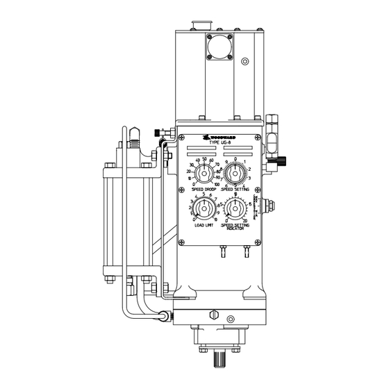
Page 9: Figure 1-1. Typical Outline Drawing Of The Ug-8D Mas With Booster Bracket
Manual 36063 UG-8D MAS mA Speed Setting Figure 1-1. Typical Outline Drawing of the UG-8D MAS with Booster Bracket Woodward... -
Page 10: Figure 1-2. Schematic Diagram Of The Ug-8D Mas With Start Fuel Limit And Terminal Shaft Indicator
UG-8D MAS mA Speed Setting Manual 36063 Figure 1-2. Schematic Diagram of the UG-8D MAS with Start Fuel Limit and Terminal Shaft Indicator Woodward... -
Page 11: Figure 1-3. Outline Drawing Of The Ug Mas Final Driver Box
Manual 36063 UG-8D MAS mA Speed Setting Figure 1-3. Outline Drawing of the UG MAS Final Driver Box Figure 1-4. Outline Drawing of the 4–20 mA Converter Box of the Terminal Shaft Indicator Woodward... -
Page 12: Figure 1-5. Top View Of Ug-8D Mas Cover
UG-8D MAS mA Speed Setting Manual 36063 Figure 1-5. Top View of UG-8D MAS Cover Woodward... -
Page 13: Chapter 2. Installation
Installation Introduction The UG-8D MAS consists of three items the cover assembly, the final driver, and the 4–20 mA converter box. Both the final driver, and the 4–20 mA converter module are packed in a box separate from the UG-8D MAS. The cover assembly is mounted on top of the governor. -
Page 14: Electrical Connections
50 mm (2 inches). The other end of the shield must be left open and insulated from any other conductor. Do not run shielded signal wires with other wires carrying large currents. See Woodward application note 50532, EMI Control for Electronic Governing Systems, for more information. -
Page 15: Stepper Motor
Manual 36063 UG-8D MAS mA Speed Setting Stepper Motor A total of five wires is required between the final driver and the stepper motor. Each wire should be 0.8 mm² (18 AWG) or larger. The cable can be a five-score screened cable or separate one or two-core screened cable. -
Page 16: Booster Bracket
Booster Bracket Mounting The booster bracket must be mounted on the UG-8D MAS with two of the four mounting screws that are used to mount the governor on the engine. On top of the booster bracket there is another screw with locking nut that will tighten down the bracket (see Figure 2-2). -
Page 17: Figure 2-2. Booster Bracket. Including Booster And Tubing
The air supply must be connected to the air inlet of the booster with the supplied connector. For more information, see Woodward manual 36684, Booster Servomotor. Terminal Return Spring The return spring lever on the terminal shaft should be located as shown in Figure 2-2. -
Page 18: Chapter 3. Operation And Adjustments
UG-8D MAS mA Speed Setting Manual 36063 Chapter 3. Operation and Adjustments Final Driver Normal Operation Once the milliamp speed setting has been properly connected, the engine may be started, stopped, and controlled according to the engine manufacturer’s instructions. The milliamp system is self-starting upon engine cranking, provided the nominal 24 Vdc is supplied to the final driver. -
Page 19: Control Adjustments
Manual 36063 UG-8D MAS mA Speed Setting 6. Connect the 24 Vdc supply power to the final driver. The stepper motor will now turn to its adjusted direction. 7. Disconnect the 24 Vdc supply power from the final driver. 8. Mount the cover on the governor while keeping the stepper motor shaft and the manual speed setting knob of the UG-8D governor at the position just determined in steps 2 and 6. - Page 20 UG-8D governor as described below. 1. Study the instructions and safety precautions in the engine manufacturer’s manual and the Woodward UG Governor manual (number 03040). 2. Remove the 24 Vdc from the final driver. 3. Start the engine.
-
Page 21: 4-20 Ma Converter Box
Control Adjustments section. 4–20 mA Converter Box The 4–20 mA converter box is connected to the UG-8D MAS as shown in the Installation section (see Figure 2-1). The adjustments of the 4–20 mA output signal must be made on the 4–20 mA converter box, and can be done on the engine while it is not running. -
Page 22: Start Fuel Limit
4–20 mA Converter Box section to adjust this. Figure 3-2. Cross Section of the Start Fuel Limit of the UG-8D MAS Governor Booster Bracket For proper adjustments of the booster, and the oil volumes of the booster, see Woodward manual 36684 Booster Servomotor. -
Page 23: Chapter 4. Description Of Operation
Manual 36063 UG-8D MAS mA Speed Setting Chapter 4. Description of Operation Final Driver The system consists of a UG-8 Dial Governor with a special cover and a separate final driver (see Figure 1-2). The cover of the UG-8 includes a stepper motor that is directly connected to the speeder screw in the UG-8 governor. -
Page 24: 4-20 Ma Terminal Shaft Indicator
300 . Booster Bracket The booster bracket is added to the UG-8D MAS to offer a complete system. This booster will give the extra pressure that is needed during the start up of the... - Page 25 Manual 36063 UG-8D MAS mA Speed Setting The tubing with connectors for the oil supply from the UG-8D to the booster, and for the pressure oil from the booster to the UG-8D, will be factory mounted on the unit. The return spring and lever on the terminal shaft is there to prevent overshooting of the start fuel limit.
-
Page 26: Chapter 5. Troubleshooting
UG-8D governor connector No oil pressure in the UG-8D system Before consulting Woodward, please check if all signals are available in the system. Milliamp Speed Setting Failures This table lists some of the possible failures in the milliamp speed setting. -
Page 27: Start Fuel Limit Failures
Manual 36063 UG-8D MAS mA Speed Setting Symptom Possible Cause Remedy Stepper motor does not Motor roll pin is disconnected from Contact Woodward. stop, and the speed the coupling, or the roll pin is setting cannot be damaged changed by the motor. -
Page 28: Chapter 6. Product Support And Service Options
A current list of Woodward Business Partners is available at www.woodward.com/directory. Product Service Options Depending on the type of product, the following options for servicing Woodward products may be available through your local Full-Service Distributor or the OEM or Packager of the equipment system. -
Page 29: Returning Equipment For Repair
To prevent damage to electronic components caused by improper handling, read and observe the precautions in Woodward manual 82715, Guide for Handling and Protection of Electronic Controls, Printed Circuit Boards, and Modules. -
Page 30: Engineering Services
Field Service engineering on-site support is available, depending on the product and location, from one of our Full-Service Distributors. The field engineers are experienced both on Woodward products as well as on much of the non- Woodward equipment with which our products interface. -
Page 31: Technical Assistance
UG-8D MAS mA Speed Setting Technical Assistance If you need to contact technical assistance, you will need to provide the following information. Please write it down here before contacting the Engine OEM, the Packager, a Woodward Business Partner, or the Woodward factory: General... -
Page 32: Revision History
UG-8D MAS mA Speed Setting Manual 36063 Revision History Changes in Revision C— Added fuse rating information for driver box (page 7) Woodward... - Page 33 Email and Website—www.woodward.com Woodward has company-owned plants, subsidiaries, and branches, as well as authorized distributors and other authorized service and sales facilities throughout the world. Complete address / phone / fax / email information for all locations is available on our website.
Need help?
Do you have a question about the UG-8D MAS and is the answer not in the manual?
Questions and answers